


416
CHAPTER 19 SERIAL INTERFACE CHANNEL 1
19.2 Serial Interface Channel 1 Configuration
Serial interface channel 1 consists of the following hardware.
Table 19-1. Serial Interface Channel 1 Configuration
Item Configuration
Register Serial I/O shift register 1 (SIO1)
Automatic data transmit/receive address pointer (ADTP)
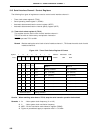
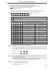
Control register Timer clock select register 3 (TCL3)
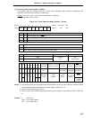
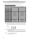
Serial operating mode register 1 (CSIM1)
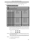
Automatic data transmit/receive control register (ADTC)
Automatic data transmit/receive interval specify register (ADTI)
Port mode register 2 (PM2)
Note
Note Refer to Figures 6-5 and 6-7 Block Diagram of P20, P21, P23 to 26 and Figures 6-6 and 6-
8 Block Diagram of P22 and P27.
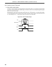
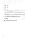
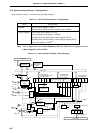
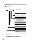
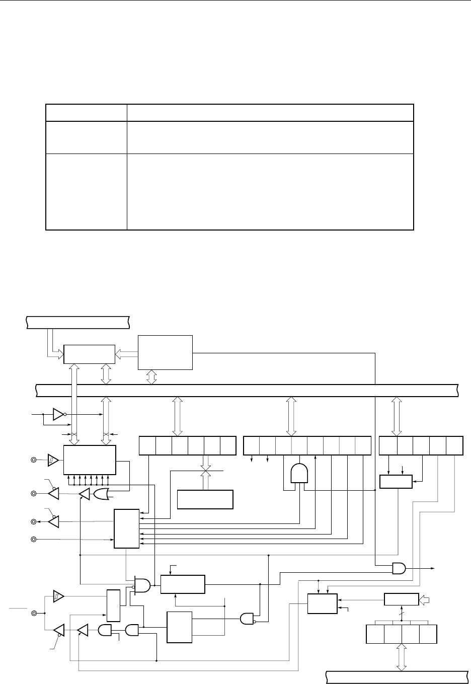
Figure 19-1. Serial Interface Channel 1 Block Diagram
RE ARLD ERCE ERR TRF STRB
BUSY
1
BUSY
0
Internal Bus
Automatic Data
Transmit/Receive
Control Register
Serial Operating
Mode Register 1
ADTI
7
ADTI
4
ADTI
3
ADTI
2
ADTI
1
ADTI
0
5-Bit Counter
Serial I/O
Shift Register 1
(SIO1)
Hand-
shake
Serial Clock
Counter
Selector
Selector
SO1/
P21
PM21
P21 Output
Latch
DIR DIR
Buffer RAM
Automatic Data
Transmit/Receive
Address Pointer
(ADTP)
SCK1/
P22
PM22
Internal Bus
TRF
P22 Output Latch
Match
ADTI0 to ADTI4
Selector
TO2
INTCSI1
Clear
SIO1 write
Q
R
S
Selector
TCL
37
TCL
36
TCL
35
TCL
34
4
Timer Clock
Select Register 3
f
xx
/2 to
f
xx
/2
8
Internal Bus
ARLD
CSIE1
DIR ATE
CSIM
11
CSIM
10
ATE
SI1/
P20
STB/
P23
PM23
BUSY/
P24
Automatic Data
Transmit/Receive Interval
Specify Register