


245
CHAPTER 9 8-BIT TIMER/EVENT COUNTERS 1 AND 2
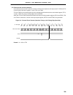
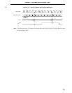
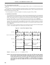
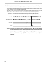
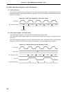
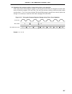
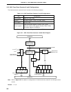
(3) Square-wave output operation
The 8-bit timer/event counters 1 and 2 operate as square wave outputs with any selected frequency at
intervals of the value preset to 8-bit compare registers (CR10 and CR20). To set the count value, set the
values of the higher 8 bits to CR20 and set the values of the lower 8 bits to CR10.
The TO2/P32 pin output status is reversed at intervals of the count value preset to CR10 and CR20 by setting
bit 4 (TOE2) of the 8-bit timer output control register (TOC1) to 1. This enables a square wave with any
selected frequency to be output.
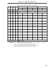
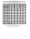
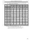
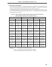
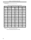
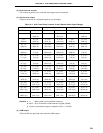
Table 9-10. Square-Wave Output Ranges when 2-Channel 8-Bit Timer/Event Counters
(TM1 and TM2) are Used as 16-Bit Timer/Event Counter
Minimum Pulse Width Maximum Pulse Width Resolution
MCS = 1 MCS = 0 MCS = 1 MCS = 0 MCS = 1 MCS = 0
2 x 1/f
X 2
2
x 1/fX 2
17
x 1/fX 2
18
x 1/fX 2 x 1/fX 2
2
x 1/fX
(400 ns) (800 ns) (26.2 ms) (52.4 ms) (400 ns) (800 ns)
2
2
x 1/fX 2
3
x 1/fX 2
18
x 1/fX 2
19
x 1/fX 2
2
x 1/fX 2
3
x 1/fX
(800 ns) (1.6
µ
s) (52.4 ms) (104.9 ms) (800 ns) (1.6
µ
s)
2
3
x 1/fX 2
4
x 1/fX 2
19
x 1/fX 2
20
x 1/fX 2
3
x 1/fX 2
4
x 1/fX
(1.6
µ
s) (3.2
µ
s) (104.9 ms) (209.7 ms) (1.6
µ
s) (3.2
µ
s)
2
4
x 1/fX 2
5
x 1/fX 2
20
x 1/fX 2
21
x 1/fX 2
4
x 1/fX 2
5
x 1/fX
(3.2
µ
s) (6.4
µ
s) (209.7 ms) (419.4 ms) (3.2
µ
s) (6.4
µ
s)
2
5
x 1/fX 2
6
x 1/fX 2
21
x 1/fX 2
22
x 1/fX 2
5
x 1/fX 2
6
x 1/fX
(6.4
µ
s) (12.8
µ
s) (419.4 ms) (838.9 ms) (6.4
µ
s) (12.8
µ
s)
2
6
x 1/fX 2
7
x 1/fX 2
22
x 1/fX 2
23
x 1/fX 2
6
x 1/fX 2
7
x 1/fX
(12.8
µ
s) (25.6
µ
s) (838.9 ms) (1.7 s) (12.8
µ
s) (25.6
µ
s)
2
7
x 1/fX 2
8
x 1/fX 2
23
x 1/fX 2
24
x 1/fX 2
7
x 1/fX 2
8
x 1/fX
(25.6
µ
s) (51.2
µ
s) (1.7 s) (3.4 s) (25.6
µ
s) (51.2
µ
s)
2
8
x 1/fX 2
9
x 1/fX 2
24
x 1/fX 2
25
x 1/fX 2
8
x 1/fX 2
9
x 1/fX
(51.2
µ
s) (102.4
µ
s) (3.4 s) (6.7 s) (51.2
µ
s) (102.4
µ
s)
2
9
x 1/fX 2
10
x 1/fX 2
25
x 1/fX 2
26
x 1/fX 2
9
x 1/fX 2
10
x 1/fX
(102.4
µ
s) (204.8
µ
s) (6.7 s) (13.4 s) (102.4
µ
s) (204.8
µ
s)
2
11
x 1/fX 2
12
x 1/fX 2
27
x 1/fX 2
28
x 1/fX 2
11
x 1/fX 2
12
x 1/fX
(409.6
µ
s) (819.2
µ
s) (26.8 s) (53.7 s) (409.6
µ
s) (819.2
µ
s)
Remarks 1. f
X : Main system clock oscillation frequency
2. MCS : Bit 0 of oscillation mode selection register (OSMS)
3. Figures in parentheses apply to operation with f
X = 5.0 MHz.