


256
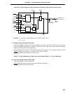
CHAPTER 10 8-BIT TIMER/EVENT COUNTERS 5 AND 6
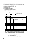
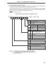
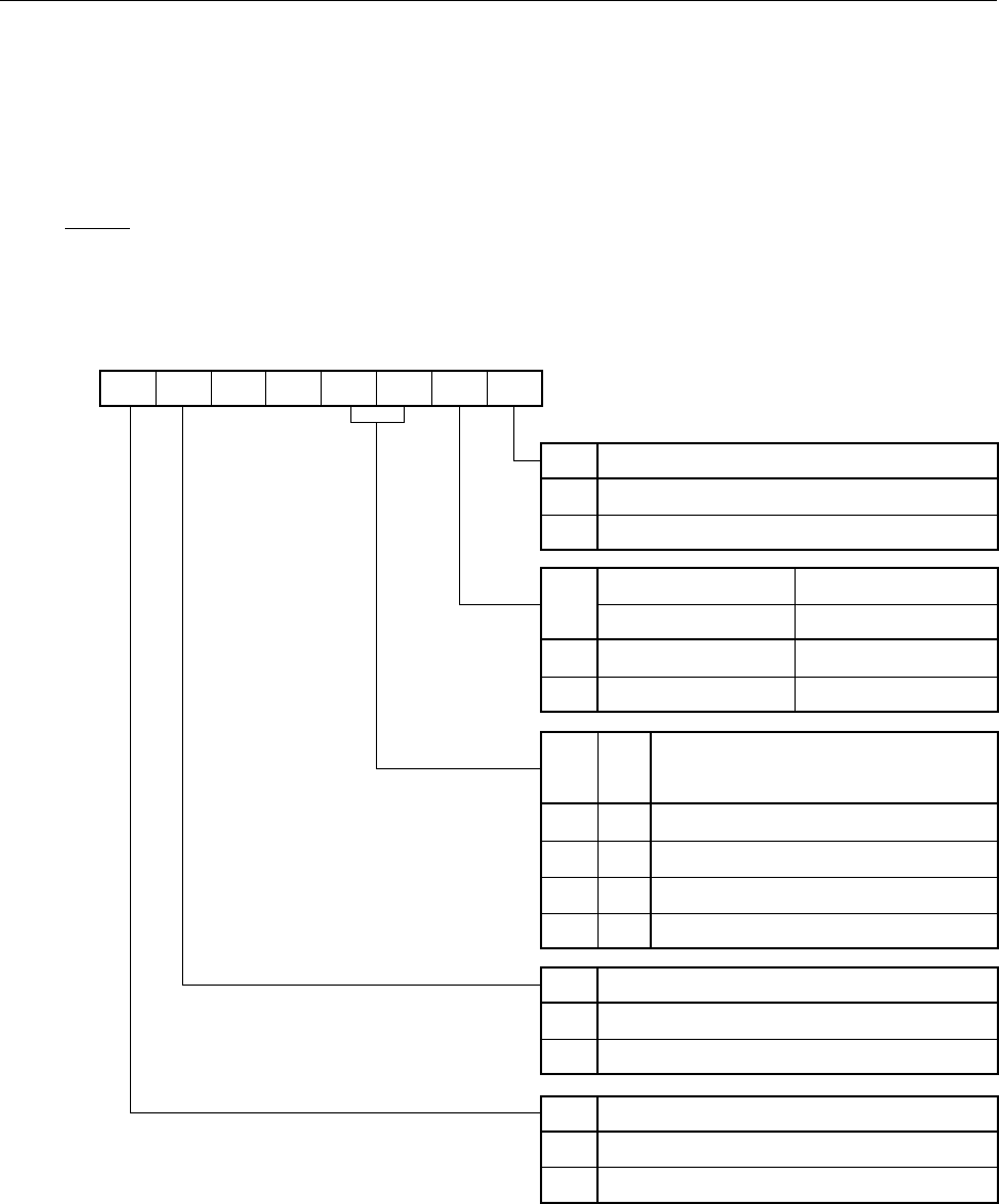
(3) 8-bit timer mode control register 5 (TMC5)
This register enables/stops operation of 8-bit timer register 5, sets the operating mode of 8-bit timer register
5 and controls operation of 8-bit timer/event counter 5 output control circuit.
It sets R-S flip-flop (timer output F/F 1,2) setting/resetting, the active level in PWM mode, inversion enabling/
disabling in modes other than PWM mode and 8-bit timer/event counter 5 timer output enabling/disabling.
TMC5 is set with a 1-bit or 8-bit memory manipulation instruction.
RESET input sets TMC5 to 00H.
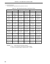
Figure 10-5. 8-Bit Timer Output Control Register Format
Cautions 1. Timer operation must be stopped before setting TMC5.
2. If LVS5 and LVR5 are read after data are set, they will be 0.
3. Set bits 4 and 5 to 0.
TCE5
TMC56
0 0 LVS5 LVR5
TMC51
TOE5
<7> 6 5 4 <3> <2> 1 <0>Symbol
TMC5
FF53H 00H R/W
Address After Reset R/W
TOE5 8-Bit Timer/Event Counter 5 Output Control
0 Output disabled (Port mode)
1 Output enabled
TMC51
0 Active high
1 Active low
In PWM Mode In Other Mode
Active level selection Timer output F/F1 control
Inversion operation disabled
Inversion operation enabled
LVS5 LVR5
00
01
10
11
8-Bit Timer/Event Counter 5 Timer
Output F/F1 Status Setting
No change
Timer output F/F1 reset (0)
Timer output F/F1 set (1)
Setting prohibited
TMC56 8-Bit Timer/Event Counter 5 Operating Mode Selection
0 Clear & start mode on match of TM5 and CR50
1 PWM mode (free-running)
TCE5 8-Bit Timer Register 5 Operation Control
0 Operation Stop (TM5 clear to 0)
1 Operation Enable