


427
CHAPTER 19 SERIAL INTERFACE CHANNEL 1
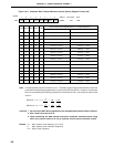
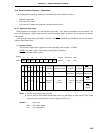
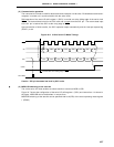
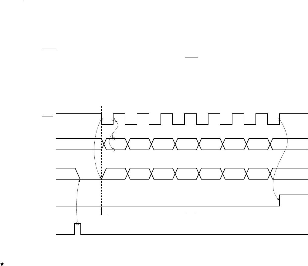
(2) Communication operation
The 3-wire serial I/O mode is used for data transmission/reception in 8-bit units. Bit-wise data transmission/
reception is carried out in synchronization with the serial clock.
Shift operation of the serial I/O shift register 1 (SIO1) is carried out at the falling edge of the serial clock
SCK1. The transmit data is held in the SO1 latch and is output from the SO1 pin. The receive data input
to the SI1 pin is latched into SIO1 at the rising edge of SCK1.
Upon termination of 8-bit transfer, the SIO1 operation stops automatically and the interrupt request flag
(CSIIF1) is set.
Figure 19-6. 3-Wire Serial I/O Mode Timings
Caution SO1 pin becomes low level by SIO1 write.
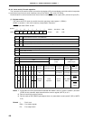
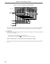
(3) MSB/LSB switching as the start bit
The 3-wire serial I/O mode enables to select transfer to start from MSB or LSB.
Figure 19-7 shows the configuration of the serial I/O shift register 1 (SIO1) and internal bus. As shown in
the figure, MSB/LSB can be read/written in reverse form.
MSB/LSB switching as the start bit can be specified with bit 6 (DIR) of the serial operating mode register
1 (CSIM1).
SI1
SCK1 12345678
DI7 DI6 DI5 DI4 DI3 DI2 DI1 DI0
SO1 DO7 DO6 DO5 DO4 DO3 DO2 DO1 DO0
CSIIF1
Transfer Start at the Falling Edge of SCK1
End of Transfer
SIO1 Write