


356
CHAPTER 17 SERIAL INTERFACE CHANNEL 0 (
µ
PD78078 SUBSERIES)
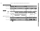
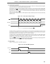
(9) Transfer start
Serial transfer is started by setting transfer data to the serial I/O shift register 0 (SIO0) when the following
two conditions are satisfied.
• Serial interface channel 0 operation control bit (CSIE0) = 1
• Internal serial clock is stopped or SCK0 is at high level after 8-bit serial transfer.
Cautions 1. If CSIE0 is set to “1” after data write to SIO0, transfer does not start.
2. Because the N-ch open-drain output must be high-impedance state for data reception,
write FFH to SIO0 in advance.
However, when the wake-up function specify bit (WUP) = 1, the N-ch open-drain output
is always high-impedance state. Thus, it is not necessary to write FFH to SIO0.
3. If data is written to SIO0 when the slave is busy, the data is not lost.
When the busy state is cleared and SB0 (or SB1) input is set to the high level (READY)
state, transfer starts.
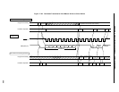
Upon end of 8-bit transfer, serial transfer automatically stops and the interrupt request flag (CSIIF0) is set.
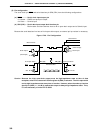
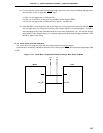
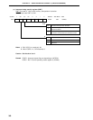
After RESET input, perform the following settings to the pins used as data input/output (SB0 or SB1) before
serial transfer of the first byte.
<1> Set 1 to the output latch of P25 and P26
<2> Set 1 to bit 0 (RELT) of the serial bus interface control register (SBIC).
<3> Set 0 to the output latch of P25 and P26, to which 1 has been set.
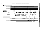
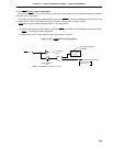
(10) How to detect the busy state in a slave
When device is in the master mode, follow the procedure below to judge whether slave device is in the busy
state or not.
<1> Detect acknowledge signal (ACK) or interrupt request signal generation.
<2> Set the port mode register PM25 (or PM26) of the SB0/P25 (or SB1/P26) pin into the input mode.
<3> Read out the pin state (when the pin level is high, the READY state is set).
After the detection of the READY state, set the port mode register to 0 and return to the output mode.
(11) SBI mode precautions
(a) Slave selection/non-selection is detected by match detection of the slave address received after bus
release (RELD = 1).
For this match detection, match interrupt (INTCSI0) of the address to be generated with WUP = 1 is normally
used. Thus, execute selection/non-selection detection by slave address when WUP = 1.
(b) When detecting selection/non-selection without the use of interrupt with WUP = 0, do so by means of
transmission/reception of the command preset by program instead of using the address match detection
method.
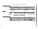
(c) In the SBI mode, the BUSY signal continues to be output after BUSY clear instruction generation to the
falling edge of the next serial clock (SCK0). If WUP is set to 1 in this period, BUSY will not be released.
Therefore, before setting WUP to 1, clear BUSY and then check that SB0 (SB1) pin has become high
level.