


524
CHAPTER 22 INTERRUPT FUNCTIONS
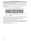
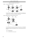
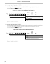
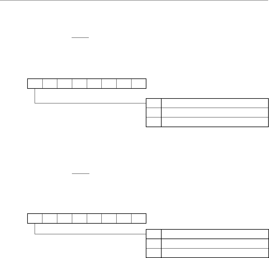
(1) Interrupt request flag register 1L (IF1L)
It indicates whether a clock timer overflow is detected or not.
It is set by a 1-bit memory manipulation instruction and 8-bit memory manipulation instruction.
It is set to 00H by the RESET signal input.
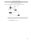
Figure 22-19. Format of Interrupt Request Flag Register 1L
Caution Set bits 5 and 6 to 0.
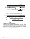
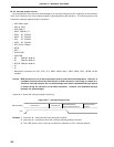
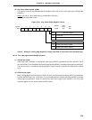
(2) Interrupt mask flag register 1L (MK1L)
It is used to set the standby mode enable/disable at the time the standby mode is released by the clock timer.
It is set by a 1-bit memory manipulation instruction and 8-bit memory manipulation instruction.
It is set to FFH by the RESET signal input.
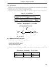
Figure 22-20. Format of Interrupt Mask Flag Register 1L
Caution Set bits 5 and 6 to 1.
<7>
WTIF
Symbol
IF1L
6
0
5
0
<4>
TMIF6
<3>
TMIF5
<2>
ADIF
<1>
TMIF2
<0>
TMIF1
Address
FFE2H 00H
After
Reset
R/W
R/W
0
1
Clock timer overflow detection flag
Not detected
Detected
WTIF
<7>
WTMK
Symbol
MK1L
6
1
5
1
<4>
TMMK6
<3>
TMMK5
<2>
ADMK
<1>
TMMK2
<0>
TMMK1
Address
FFE6H FFH
After
Reset
R/W
R/W
0
1
Standby mode control by clock timer
Enables releasing the standby mode.
Disables releasing the standby mode.
WTMK