


208
CHAPTER 8 16-BIT TIMER/EVENT COUNTER
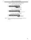
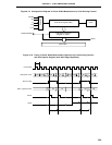
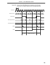
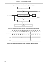
(3) Pulse width measurement with free-running counter and two capture registers
When the 16-bit timer register (TM0) is operated in free-running mode (see register settings in Figure 8-22),
it is possible to measure the pulse width of the signal input to the TI00/P00 pin.
When the edge specified by bits 2 and 3 (ES10 and ES11) of external interrupt mode register 0 (INTM0)
is input to the TI00/P00 pin, the value of TM0 is taken into 16-bit capture/compare register 01 (CR01) and
an external interrupt request signal (INTP0) is set.
Also, on the inverse edge input of that of the capture operation into CR01, the value of TM0 is taken into
16-bit capture/compare register 00 (CR00).
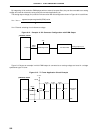
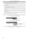
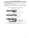
Either of two edge specifications can be selected—rising or falling—as the valid edges for the TI00/P00 pin
by means of bits 2 and 3 (ES10 and ES11) of INTM0.
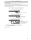
For TI00/P00 pin valid edge detection, sampling is performed at the interval selected by means of the
sampling clock selection register (SCS), and a capture operation is only performed when a valid level is
detected twice, thus eliminating noise with a short pulse width.
Caution If the valid edge of TI00/P00 is specified to be both rising and falling edge, capture/compare
register 00 (CR00) cannot perform the capture operation.
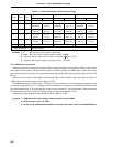
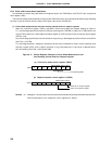
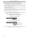
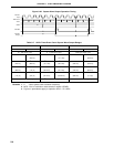
Figure 8-22. Control Register Settings for Pulse Width Measurement with
Free-Running Counter and Two Capture Registers
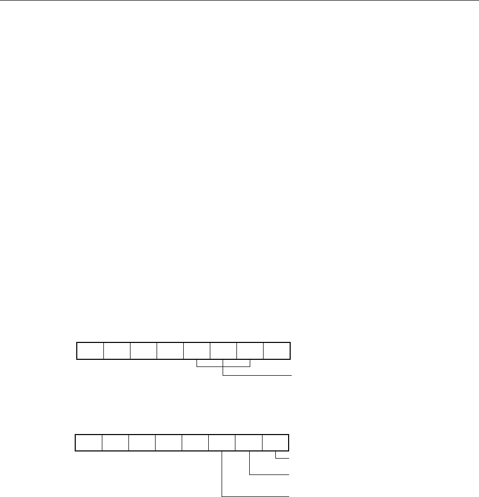
(a) 16-bit timer mode control register (TMC0)
(b) Capture/compare control register 0 (CRC0)
Remark 0/1: Setting 0 or 1 allows another function to be used simultaneously with pulse width measurement.
See the description of the respective control registers for details.
TMC0 00/1100000
OVF0TMC01TMC02TMC03
Free-Running Mode
CRC0 11100000
CRC00CRC01CRC02
CR00 set as capture register
Captured in CR00 on invalid edge of
TI00/P00 Pin
CR01 set as capture register