


2-18
Cisco MGX 8950 Hardware Installation Guide
Release 3, Part Number 78-14147-02 Rev. A0, November 2002
Chapter 2 Preparing for Installation
Site Requirements
those of the Cisco MGX 8950 circuit breaker with a medium trip delay. The Cisco MGX 8950 switch
uses a 30 A, 2-pole circuit breaker for each AC input. We recommend that the site have a 30 A, 2-pole
AC circuit breaker with a long trip delay at each branch circuit.
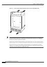
Note For more information about the AC power supply tray, see the “AC Power Supply Tray” section on
page 1-45.
Tip Check the power at your site to ensure that you are receiving “clean” power (free of spikes and noise).
Install a power conditioner if necessary.
Caution Consult Cisco Customer Service if the plans for MGX 8950 AC power include an uninterruptible power
source (UPS). We recommend a UPS with a low output impedance and the capacity to provide the
necessary fault current to trip the protection devices. If the UPS cannot have the capacity to provide the
fault current, the UPS must be equipped with a fault bypass switch that can trip the protection devices
through the utility power. Do not use a UPS or any power source with a Ferro-Resonant transformer.
Caution For mission-critical applications, we recommend that you use the dual AC power input tray with dual
AC power cords, so that there can be no single or primary power failure.
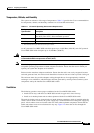
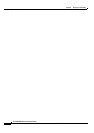
The power receptacles to which the switch connects must be of the grounding type. The grounding
conductors that connect to the receptacles should connect to protective earth at the service equipment.
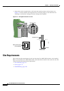
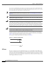
Figure 2-5 shows the hookup schematic in the three-wire wall plug.
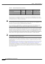
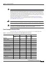
For AC power cord details (part numbers and countries), see Table 2-6.
Figure 2-5 Schematic of AC Plug Wiring
DC Power
DC power is supplied to the Cisco MGX 8950 through one or two DC PEMs. Each DC PEM must be
connected to a dedicated 100 A regulated source. Each branch circuit must have a 100 A circuit breaker
at the source. Wires connecting the PEMs to the sources should be capable of carrying 100 A. A
6 AWG
(10
square mm) copper wire is recommended. Consult the local or national codes for conductor sizing
for DC supply connections if necessary.
66285
L2
L1
180 - 254 VAC