


2-12
Cisco MGX 8950 Hardware Installation Guide
Release 3, Part Number 78-14147-02 Rev. A0, November 2002
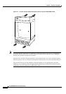
Chapter 2 Preparing for Installation
Site Requirements
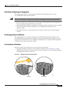
Vibration
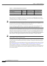
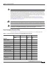
Table 2-1 describes the Cisco recommendations for vibration conditions.
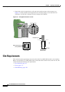
Space
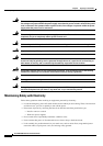
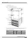
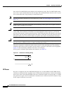
You can install the following Cisco MGX 8950 switch components in a rack (as shown in Figure 2-3):
• Exhaust plenum
• Upper fan tray
• Cisco MGX 8950 switch
• Lower fan tray
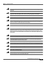
Ta b l e 2-1 Vibration Conditions
Category NEBS Description MDVT Description
Earthquake • No damage to the switch when tested
to earthquake waveform.
• 75-mm maximum single amplitude
deflection.
• Frame-level natural mechanical
resonant frequency > 2 Hz.
• Frame-level natural mechanical
resonant frequency > 6 Hz.
• Product must function before and
after each axis.
• Product must operate without loss of
service during earthquake testing.
• None
Office • 3 axis swept-sine
• 5 Hz to 100 Hz to 5 Hz
• 0.1 G, 0.1 octaves/min
• 0.41 Grms, 3 to 500 Hz
• Spectral break points of
0.0005 G
1
/Hz at 10 Hz and 200 Hz
• 5 dB/octave roll off at each end
• 2 hrs per axis of operation
1. Office Product—More than 2m from regularly inhabited positions.
Transportation • For rail, truck, ship, 5 to 100 Hz,
0.1
octave/min, 0.5 G
• For rail, truck, ship, jet, reciprocating
or turbo prop aircraft, 100 to 500 Hz,
0.25 octave/min, 1.5 G
• 3 to 300 Hz, 0.5G
2
• 30 min per axis
2
2. Cisco Package Test Specification
Non-Operational • None • 1.12 Grms, 3 to 500 Hz
• Spectral break points of
0.0065
G
1
/Hz at 10 Hz and 100 Hz
• 5dB/octave roll off at each end
• 30 minutes in each of 3 axes