


4-11
Cisco MGX 8950 Hardware Installation Guide
Release 3, Part Number 78-14147-02 Rev. A0, November 2002
Chapter 4 Maintaining the Cisco MGX 8950 Switch
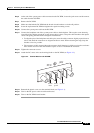
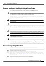
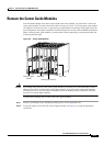
Remove the Center Guide Modules
Remove the Center Guide Modules
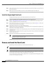
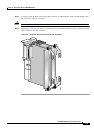
To install double-height cards where single-height cards were installed, you will need to remove the
center guide modules, located at the front of the card cage (see
Figure 4-5). Each center guide module
encompasses two front card slots, so plan front card replacements accordingly. Each empty slot in the
new configuration will require installation of a blank faceplate for air flow control and EMI containment.
When removing center guide modules, you must remove them sequentially, starting from the left and
working toward the right.
Figure 4-5 Center Guide Module
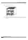
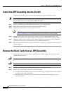
Caution Even though most portions of the vertical guide brackets are insulated, we recommend that you turn
off the power before you remove the center guide modules. If you remove the center guide modules
while the power is on, you may short out the adjacent cards by making contact with the non-insulated
leg ends of a vertical support bracket.
Complete the following steps to remove the center guide modules:
Step 1 Connect a grounding strap to the ESD grounding jack or to the equipment rack.
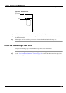
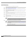
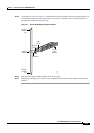
Step 2 Loosen the captive screw from the vertical support bracket (see Figure 4-6) using the appropriate
screwdriver.
17673
Door latch
Vertical support
bracket
Bulkhead
Center guide module