


B-5
Cisco MGX 8950 Hardware Installation Guide
Release 3, Part Number 78-14147-02 Rev. A0, November 2002
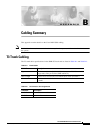
Appendix B Cabling Summary
External Alarm Cabling
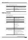
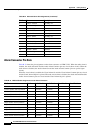
Bits Clock Connector Pin Outs
Table B-10 lists the pinouts for the RJ48 BITS clock connector using T1 BITS. Make sure that the 100
ohm termination is selected when configuring the clocks. You will need to connect only the RX Ring,
RX
tip, and the ground signals.
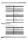
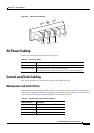
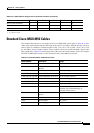
External Alarm Cabling
The external alarm cable connects to the alarm connector on the PXM-UI-S3 card. See Table B-11 for
the physical characteristics of the cable and Table B-12 for the pinouts.
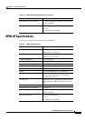
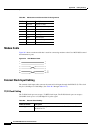
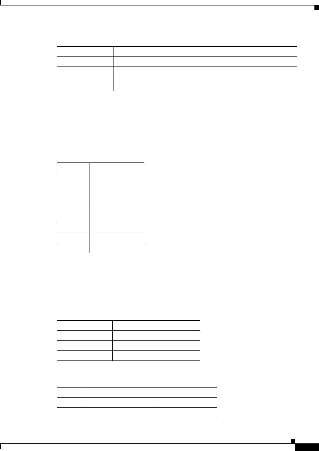
Cable Connector RJ45 for T1.
Max. Cable Length 533 ft. (162 m) maximum between the Cisco MGX 8950 switch and the
first repeater or CSU. Selection of cable length equalizers is used. Wire
build-out is required.
Table B-9 External Clock Cabling
Cable Parameter Description
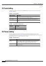
Ta b l e B-10 RJ48 BITS Clock Connector Pin Outs
Pin No. Signal
1 TX Ring
2 TX Tip
3 Ground
4 RX Ring
5 RX Tip
6 Ground
7 TTP Ring
8 TTP Tip
Ta b l e B-11 External Alarm Cabling
Cable Parameter Description
Interface Dry-contact relay closure.
Wire 24 AWG, shielded, 6-pair.
Connector DB-15, Subminiature, male.
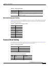
Ta b l e B-12 Network Alarm Pin Assignments
Pin No. Alarm Description
1 Audible—Critical Normally on
2 Visual—Critical Normally on