


1-6
Cisco MGX 8950 Hardware Installation Guide
Release 3, Part Number 78-14147-02 Rev. A0, November 2002
Chapter 1 Product Overview
Cisco MGX 8950 Modules Overview
• The port number assigned to the working line must be lower than the port number assigned to the
protection line. For example, the working line could be on port 3 and the protection line on port 4.
If the protection line is on port 2, do not assign the working line to port 3.
• The switches at both ends of the APS lines must be configured for APS, and the role of each line
(working or protection) must be the same at both ends of the line.
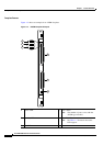
1:N Card Set Redundancy
1:N card set redundancy occurs when several active module card sets and a standby module card set are
present in the switch. When an active module fails, the packets destined for the failed module are
switched over to the standby module. The standby module and the back card that serviced the failed
module become the active card set.
The service modules in a 1:N card set redundancy group must be the same type (RPM-XF or RPM-PR).
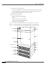
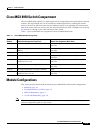
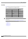
Cisco MGX 8950 Modules Overview
Table 1-2 lists the modules that support the Cisco MGX 8950 switch.
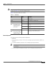
Ta b l e 1-2 Cisco MGX 8950 Module Support
Front Card Back Card
PXM45/B User interface back card:
• PXM-UI-S3
Hard drive card:
• PXM-HD
XM-60 No back cards
AXSM-1-2488/B • SMFLR-1-2488/B
• SMFSR-1-2488/B
• SMFXLR-1-2488/B
AXSM-4-622/B • SMFIR-2-622/B
• SMFLR-2-622/B
AXSM-16-155/B • MMF-8-155-MT/B
• SMB-4-155
• SMFIR-8-155-LC/B
• SMFLR-8-155-LC/B
AXSM-16-T3E3/B • SMB-8E3
• SMB-8T3
RPM-PR-256 • MMF-FE
• RJ45-4E/B
• RJ45-FE