


B-2
Cisco MGX 8950 Hardware Installation Guide
Release 3, Part Number 78-14147-02 Rev. A0, November 2002
Appendix B Cabling Summary
E3 Trunk Cabling
E3 Trunk Cabling
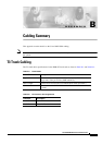
A trunk cable connects each E3 port on the SMB-8E3 back card to a E3 port. See Table B-3 and
Table B-4 for details.
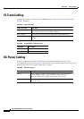
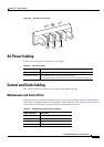
DC Power Cabling
DC power connections are made to the DC power entry modules (PEMs) at the rear of the
Cisco
MGX 8950 switch. (See Figure B-1.) See Table B-5 for acceptable cable and wire types. Cisco
normally does not provide wiring for DC-powered systems.
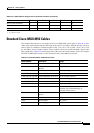
Ta b l e B-3 E3 Trunk Cables
Cable Parameter Description
Type 75-ohm coaxial cable (RG-59 B/U for short runs, AT&T 734A for
longer runs). Two per E3 line (XMT and RCV).
Max. Length 450 feet max. between the Cisco MGX 8950 switch and DSX-3.
Connector Terminated in male SMB. Rx is received from trunk; Tx is transmitted
to trunk.
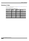
Ta b l e B-4 E3 Connector Pin Assignments
Connector Description
Rx SMB Receive E3 from trunk
Tx SMB Transmit E3 to trunk
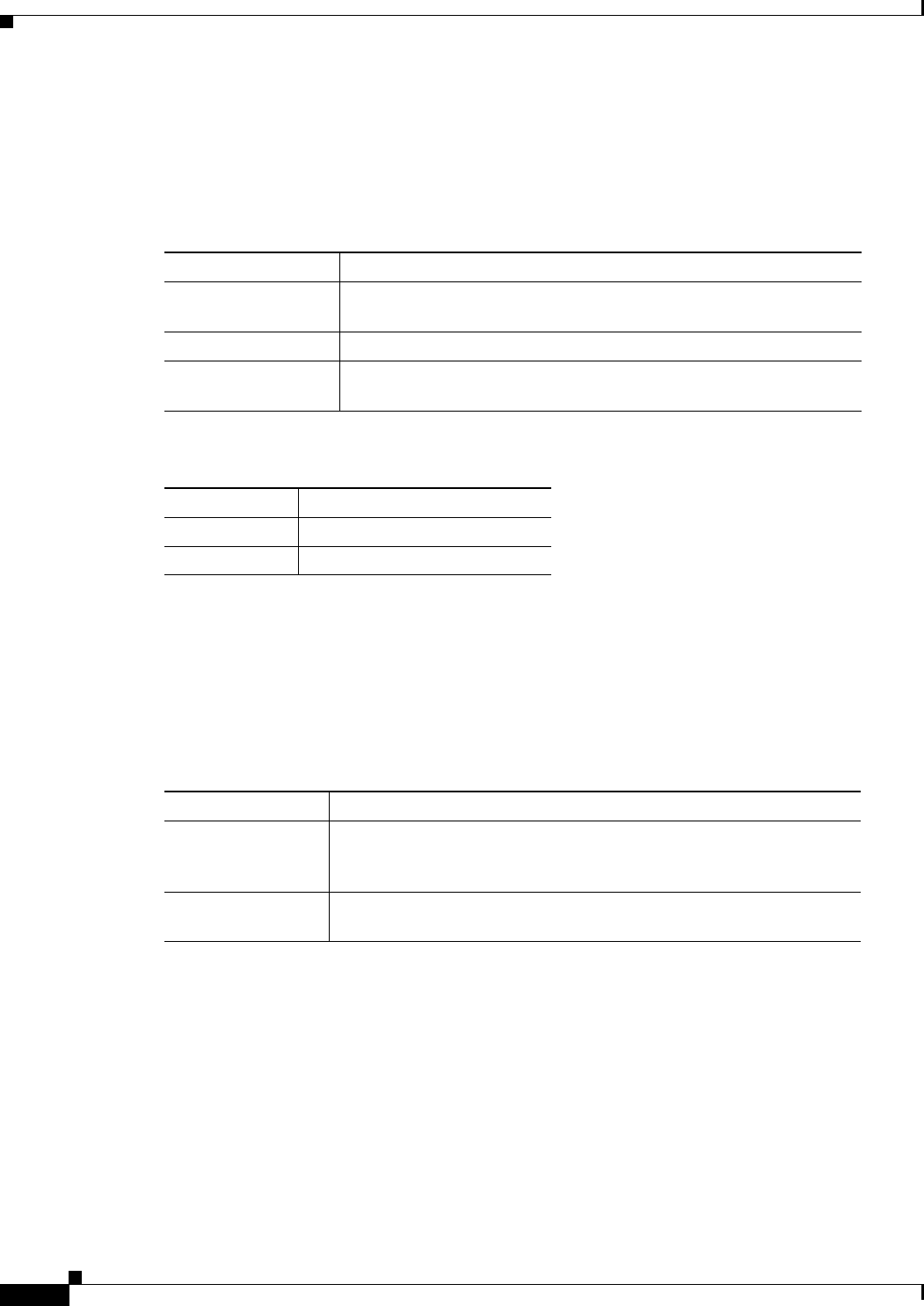
Ta b l e B-5 DC Power Wiring
Cable Parameter Description
Wiring Three conductor, 6 AWG recommended wire gauge, min. 60 degrees
Celsius insulation rating, copper conductors only. Panduit LC
AS6-10-L terminal lug or equivalent to fit no. 10-32 screws.
Connection Panduit terminal lug (part number LC AS6-10-L) or equivalent to fit
no.
10-32 screws.