


3-32
Cisco MGX 8950 Hardware Installation Guide
Release 3, Part Number 78-14147-02 Rev. A0, November 2002
Chapter 3 Installing a Cisco MGX 8950
Installation Procedures
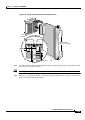
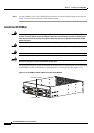
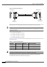
Step 4 Use four mounting screws and a Phillips-head screwdriver to bolt the exhaust plenum in the rack. See
Figure 3-4 for the correct placement of the exhaust plenum.
Install the DC PEM(s)
Warning
Before performing any of the following procedures, ensure that power is removed from the DC
circuits. To ensure that all power is removed, locate the circuit breakers or fuses on the DC power
lines that service the DC circuits. Turn OFF the DC power line circuit breakers and remove the DC
power line fuses.
Warning
Before working on a system that has an On/Off switch, turn OFF the power and unplug the power cord.
Warning
Never install an AC power module and a DC power module in the same chassis.
Warning
Before working on a chassis or working near power supplies, unplug the power cord on AC units;
disconnect the power at the circuit breaker on DC units.
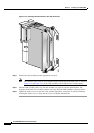
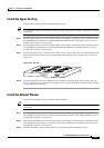
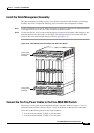
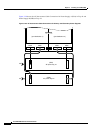
For a DC-powered system, install the DC PEMs at the back of the air intake plenum. If you install only
one DC-PEM, install it on the bottom as viewed from the rear of the plenum. (See
Figure 3-15.)
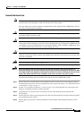
Figure 3-15 DC-PEMs Installed in Back of the Air Intake Module
-48V D
C
50A
D
C
D
C
-48V
D
C
50A
-48V
R
TN
J2
J1
-48V
DC
50A
-4
8V
RTN
-48V
DC
50A
-48V
DC
50A
-48V
R
TN
J2
J1
-4
8V D
C
50A
-48V
R
TN
43975
Secondary PEM
Primary PEM