


4-9
Cisco MGX 8950 Hardware Installation Guide
Release 3, Part Number 78-14147-02 Rev. A0, November 2002
Chapter 4 Maintaining the Cisco MGX 8950 Switch
Remove and Install the Back Cards
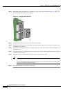
Caution Proper ESD protection is required whenever you handle Cisco equipment. Installation and maintenance
personnel should be properly grounded through the use of grounding straps to eliminate the risk of ESD
damage to the equipment. Modules are subject to ESD damage whenever they are removed from
the chassis.
Caution If the AXSM-1-2488 or AXSM-1-2488/B front cards are installed with incorrect back cards, you may
damage the cards.
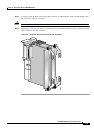
Caution To prevent damage to components on the bottom side of a card, support the faceplate and keep the card
level while sliding it into the chassis.
Caution Cards must be inserted in the correct slot positions. If service module back cards are installed in the
wrong slots, electrical damage can occur. If a service module back card is inserted into a PXM back card
slot, damage to the card and backplane can result.
Caution If you accidentally attempt to insert a service module back card into a PXM back card slot and then have
difficulty operating the chassis, examine the backplane pins and back card connector to see if they have
been bent or damaged.
Warning
Blank faceplates and cover panels serve three important functions: they prevent exposure to
hazardous voltages and currents inside the chassis; they contain electromagnetic interference (EMI)
that might disrupt other equipment; and they direct the flow of cooling air through the chassis. Do not
operate the system unless all cards, faceplates, front covers, and rear covers are in place.
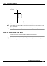
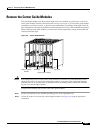
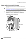
Remove the Back Cards
Complete the following steps to remove back cards from the chassis:
Step 1 Connect a grounding strap to the ESD grounding jack.
Step 2 Mark and disconnect all cables and wires from the back card.
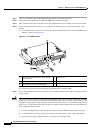
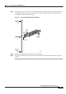
Step 3 Use the flat-head or Phillips tip of the 3-in-1 tool to loosen the two captive screws located on the top
and bottom of the back card faceplate.
Step 4 Pull each of the two extractor levers, located at the top and bottom of the faceplate, out to the
horizontal
position.
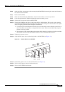
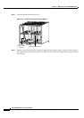
Step 5 Pull evenly on the two extractor levers to remove the back card from the card cage.
Step 6 Either replace the back card that you removed or cover the empty slot with a blank faceplate.