


1-19
Cisco MGX 8950 Hardware Installation Guide
Release 3, Part Number 78-14147-02 Rev. A0, November 2002
Chapter 1 Product Overview
System Hardware Components
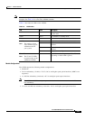
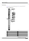
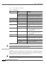
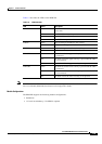
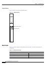
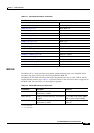
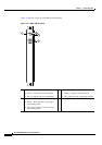
Table 1-9 describes the LEDs on the RPM-PR.
Note For information on RPM-PR software features and configurations, refer to the Cisco MGX Route
Processor Module (RPM-PR) Installation and Configuration Guide.
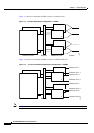
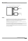
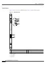
Module Configurations
The RPM-PR supports the following module configurations:
• Standalone
• 1:N card set redundancy—No SRM is required
Ta b l e 1-9 RPM-PR LEDs
LED Status Description
CPU OK Green The RPM-PR card set (front card and back cards) is in the
active state.
Yellow The RPM-PR is in standby mode.
Red The RPM-PR has failed.
Off The CPU is not operational.
CB TX Green Cells are being transmitted to the cell bus.
Off Cells are not being transmitted to the cell bus.
CB RX Green Cells are being received from the cell bus.
Off Cells are not being received from the cell bus.
LM1 OK Green The back card in the upper rear bay is present and the cable
is connected.
Red The back card in the upper rear bay is present but the cable
is not connected.
Off The back card in the upper rear bay is not present.
LM2 OK Green The back card in the lower rear bay is present and the cable
is connected.
Red The back card in the lower rear bay is present but the cable
is not connected.
Off The back card in the lower rear bay is not present.