


B-4
Cisco MGX 8950 Hardware Installation Guide
Release 3, Part Number 78-14147-02 Rev. A0, November 2002
Appendix B Cabling Summary
Control and Clock Cabling
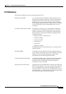
Modem Cable
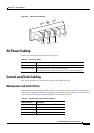
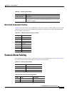
Figure B-2 shows a modem cable that is used for connecting modems to the Cisco MGX 8950 control
and maintenance ports.
Figure B-2 Null Modem Cable
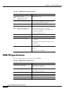
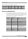
External Clock Input Cabling
The external clock input cable connects the external clock inputs through the PXM-UI-S3. The clock
may be 1.544 Mbps for 2.048 Mbps. (See
Table B-9 through Table B-15.)
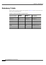
T1/E1 Clock Cabling
The T1 RJ48 clock port can accept a T1 BITS clock input. The E1 RJ48 clock port can accept a
2.048
MHz clock sync or a 2.048 Mbps E1 bi-polar signal.
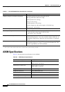
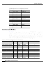
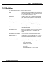
Ta b l e B-8 Maintenance and Control Port Pin Assignments
Pin No. Name Description
1 RTS out Request to Send
2 DTR out Data Terminal Ready
3 TxD Transmit Data
4 GND Chassis ground
5 GND Chassis ground
6 RxD Receive Data
7 DSR Data Set Ready
8 CTS Clear to Send
1
7
2
3
6
20
1
7
2
3
6
20
S6189
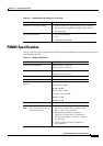
Ta b l e B-9 External Clock Cabling
Cable Parameter Description
Cable Type 22 AWG, twisted pair w/shield. 100 ohm for T1; 100 ohm for T1;
120
ohm for E1.