


4-16
Cisco MGX 8950 Hardware Installation Guide
Release 3, Part Number 78-14147-02 Rev. A0, November 2002
Chapter 4 Maintaining the Cisco MGX 8950 Switch
Install the APS Assembly into the Switch
Install the APS Assembly into the Switch
Complete the following steps to install the APS assembly into the Cisco MGX 8950 switch:
Note An APS assembly consists of two back cards, an primary card and a secondary card, which are connected
using an APS connector (Cisco Part Number MGX-APS-CON).
Step 1 Connect a grounding strap to the ESD grounding jack or to the equipment rack.
Step 2 Verify that the back cards are securely connected to the APS connector.
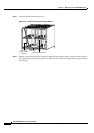
Step 3 Position the APS assembly into the appropriate card slots.
Note The extractor levers must be closed (flush with the vertical edge of the back cards, as shown in
Figure 4-8 and Figure 4-9) or the APS assembly will not slide into the chassis properly.
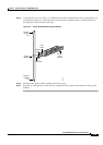
Step 4 Slide the APS assembly all the way into the slot until it is properly seated in the backplane. The
faceplates of the back cards are flush with the card cage when the APS assembly is properly
seated.
Step 5 Tighten the captive screws on the back cards with the appropriate screwdriver. If you have difficulty
inserting the captive screws, verify that the screws are aligned with the holes.
Step 6 Refer to the appropriate software configuration guide for commands to verify that the APS connector is
installed properly.
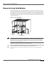
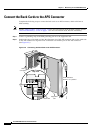
Remove the Back Cards from an APS Assembly
Complete the following steps to remove back cards from an APS assembly and to remove the APS
connector from the switch:
Caution Do not use a power screwdriver on captive screws.
Caution A rocking motion during connector mating can bend or damage the APS connector pins.
Step 1 Connect a grounding strap to the ESD grounding jack or to the equipment rack.
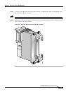
Step 2 Remove one of the back cards connected to the APS assembly
a. Use the flat-head or Phillips tip of the 3-in-1 tool to loosen the two captive screws located on the top
and bottom of the back card faceplate.
b. Pull each of the two extractor levers, located at the top and bottom of the faceplate, out to the
horizontal position.