


3-16
Cisco MGX 8950 Hardware Installation Guide
Release 3, Part Number 78-14147-02 Rev. A0, November 2002
Chapter 3 Installing a Cisco MGX 8950
Installation Procedures
Warning
Before working on a chassis or working near power supplies, unplug the power cord on AC units;
disconnect the power at the circuit breaker on DC units.
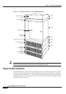
Remove the AC Power Supplies from the AC Power Tray
Tip Before removing the AC power supplies from the tray, record the location of each power supply.
Complete the following steps to remove an AC power supply from the AC power tray:
Step 1 Place the AC power supply tray on a flat and stable surface (for example, a table top).
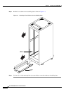
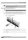
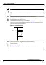
Step 2 Insert a small flat-blade (.20 inch wide maximum) screwdriver in the access hole at the top of the air
intake grille, as shown in
Figure 3-7. Then, rotate the screwdriver in either direction until the latch opens.
Figure 3-7 Removing an AC Power Supply
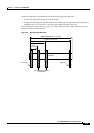
Step 3 Tilt the air inlet grill down to about a 45-degree angle, then lift the grill out and set it aside. This action
exposes the hinged door that serves as the power supply retainer bracket.
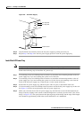
Step 4 With a flat-blade screwdriver, unscrew the captive retainer screw in the center of the hinged door and tilt
the door down.
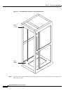
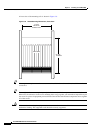
Step 5 Loosen the captive screw at the bottom front of the power supply that you want to remove, as shown in
Figure 3-8.
44142
AC
DC
1200W
A
C
DC
1200W
AC
DC
1200W
A
C
D
C
1200W
Released
air intake
grille
Access
hole
Latch
Power
supply