


B-7
Cisco MGX 8950 Hardware Installation Guide
Release 3, Part Number 78-14147-02 Rev. A0, November 2002
Appendix B Cabling Summary
Standard Cisco MGX 8950 Cables
Standard Cisco MGX 8950 Cables
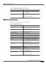
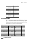
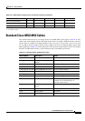
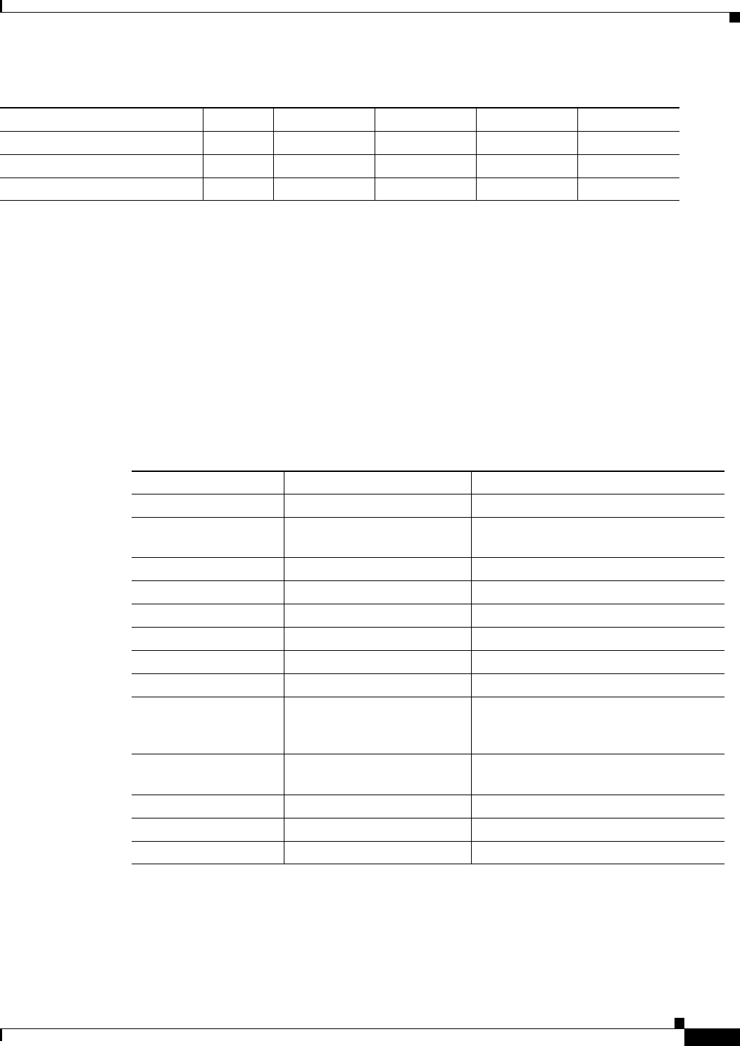
The standard cables that Cisco can supply for the Cisco MGX 8950 system appear in Table B-14. The
suffix to the model number indicates the length of the cable. For example, 5610-50 indicates a 50-foot
cable. Cables are available in standard lengths of 10 ft. (3 m), 25 ft. (7.6 m), 50 ft. (15 m), 75
ft. (22.8
m), and 100 ft. (30 m). Lengths of 100 ft. (30 m) to 600 ft. (183 m) are available through a special order.
Where applicable, Table B-14 includes the gender of the connector and the number of pins. For example,
EIA/TIA-232/M25-M25 indicates a cable terminated with a male DB25 at both ends.
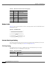
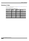
Minor Visual Alarm On 7 — — S O
Minor Visual Alarm Common 15 — — Common Common
Minor Visual Alarm Off 8 — — O S
1. S = Signal is shorted with Common
2. O = Signal is opened
Table B-13 PXM-UI-S3 Pin Assignment on the Alarm Connector (continued)
Pin Name Pin No. Audio Enable Audio Disable Visual Enable Visual Disable
Ta b l e B-14 Standard Cables Available from Cisco
Model Number Description Usage
CAB-T3E3-PL-AD-6 75 Ω coax/SMB-BNC, 6 feet T3 or E3 trunk interface
CAB-5681-06 ASSY CBL SMB(M) to
BNC(F)
T3 or E3 trunk interface
CAB-5698-6 T3/E3 SMB to SMB Posi-Lok Redundant usage
CAB-T3E3-PL-AD-6 Posi-lok SMB to BNC 6 Ad T3 or E3 trunk interface
CAB-T3E3-PL-CE-AD T3/E3 SMB-BNC Posi-lok A T3 or E3 trunk interface
CAB-T3E3-PL-CE-Y T3/E3 SMB-BNC Posi-lok Y Redundant usage
CAB-T3E3-PL-Y Posi-lok SMB to BNC Y Ca Redundant usage
CAB-T3E3-PL-Y-6 Posi-lok SMB to BNC 6 Y Redundant usage
5620 EIA/TIA-232/M25-F25 PXM-UI-S3 maintenance port to control
terminal, Cisco WAN Manager, or
external window device
5621 EIA/TIA-232/M25-M25
special
Control or maintenance port to modem
5601 Ground cable DC power
5670 Molex-pigtail DC power
5671 Spade lug-pigtail DC power