


3-35
Cisco MGX 8950 Hardware Installation Guide
Release 3, Part Number 78-14147-02 Rev. A0, November 2002
Chapter 3 Installing a Cisco MGX 8950
Installation Procedures
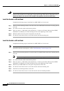
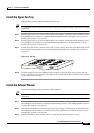
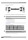
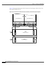
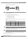
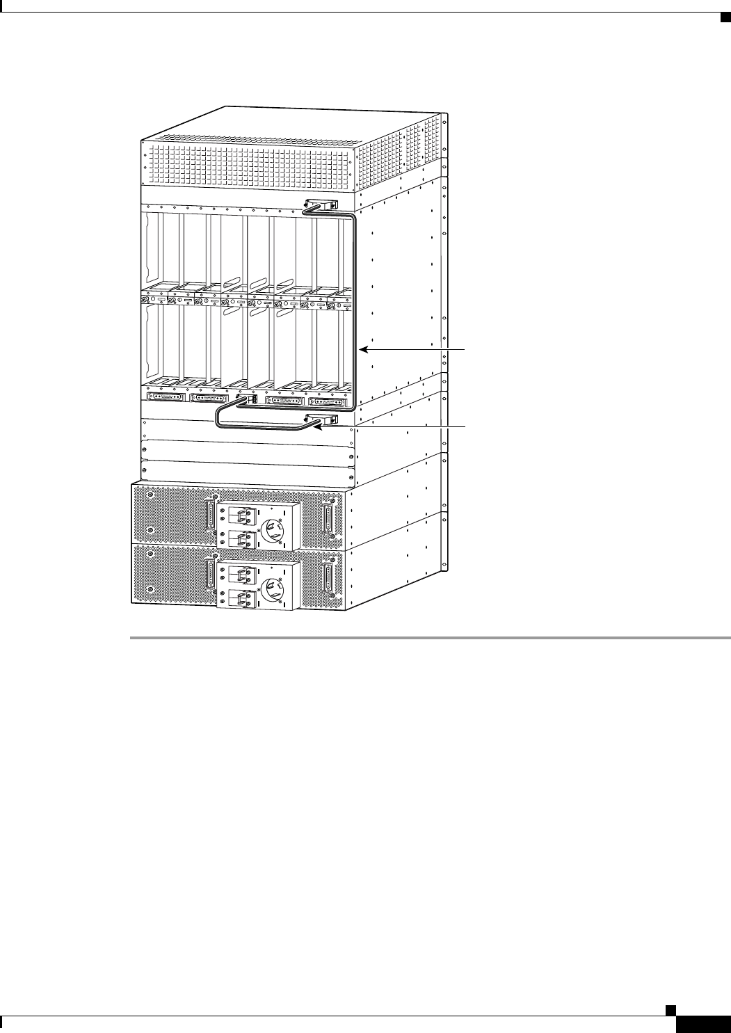
Figure 3-18 Fan Power Connections (AC-Powered Node Shown)
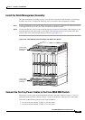
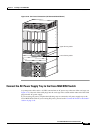
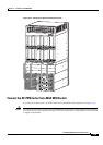
Connect the AC Power Supply Tray to the Cisco MGX 8950 Switch
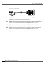
A system power cable carries –48 VDC current from an AC power tray to the rear of the card cage (see
Figure 3-21). One end of the cable plugs into the card cage in the switch and the other end of the cable
plugs into the AC power supply.
If you are using AC power, complete the following steps to connect the AC power supply tray to the
Cisco MGX 8950 switch. If you are using DC power, proceed to the
“Connect DC Power to the Switch”
section on page 3-49.
A
C
IN
A
C
IN
D
C
O
U
T
A
C
IN
A
C
IN
D
C
O
U
T
44393
Upper fan tray cable
Lower fan tray cable