


C-6
Cisco MGX 8950 Hardware Installation Guide
Release 3, Part Number 78-14147-02 Rev. A0, November 2002
Appendix C Earthing and Bonding Recommendations
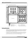
Bonding Networks
In this appendix, the energy sources that cause concern are referred to as emitters. The people and
equipment that can suffer adversely from these emitters are referred to as susceptors.
The coupling between an emitter and a susceptor can be characterized as a transfer function. The purpose
of a BN is to reduce the magnitude of the transfer function to an acceptable level. Reducing the
magnitude of the transfer function is achieved through the design of the BN; specifically, in the way that
MBNs and IBNs are attached to the CBN. The practical aspects of this design are discussed below.
A BN can also function as a return conductor for signaling applications, as a connection to earth for
ground return signaling, and as a path for power fault currents. A BN that can handle large currents can
rapidly de-energize faulted power circuits.
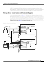
Digital System Grounding
For the Cisco MGX 8950 switch, Cisco policy has been to ground the return of the 48 VDC directly to
the frame at the backplane. This method of grounding prevents transient currents caused by lightning or
power surges from entering the system through the backplane, upsetting system performance and
possibly damaging components.
Isolating grounds like this one, using only analog methods, does not address the current high-speed
digital system requirements. Digital systems today have such high speeds and large bandwidths that they
now produce frequencies with harmful effects. Consequently, digital systems now require multi-point
grounding.
Isolation using analog methods provides at the physical level of our interfaces and not at the
power-supply end.
The bus currents and isolation parasitic capacitance that are represented by the 48 VDC side of the
system create much greater threat levels to the backplane of our systems, which have embedded
communication buses distributed through them. To mitigate these effects, you must bond and provide the
lowest possible impedance to ground at the backplane. Capacitors used to isolate the DC common paths
are inadequate at RF frequencies outside the backplane structure. Therefore, isolation must be kept to
multi-point ground the 48 VDC return to chassis and logical ground at the backplane level of the Cisco
equipment.
Bellcore GR-1089, 1997 edition, speaks of these recent challenges in Chapter 9. This new thinking is
the outgrowth of the ITU-T K.27 recommendations released in 1991. The bonding of meshed bonding
networks and the digital high speeds dictate the eventual acceptance of this new philosophy on a
universal basis. The CE-Mark requirements for the induced effects of transient and power surge lightning
cannot be met with large, high impedance (150 M ohms or greater) grounding wires. These standard
grounding conductors have a very high impedance at frequencies grater than 10 MHz.
The grounding of the frames and the mesh bonding network must be effective over a frequency range of
60 Hz to 100 GHz according to Bellcore requirements. 30 cm of wire represents 30 nH of inductance.
This represents 2 ohms of reactance at a frequency of 30 MHz. This high impedance would be a large
change from earth reference if earth were several stories below the equipment installation. A four-story
building would represent 1000 ohms above ground during a 30 MHz-frequency disturbance in this
example. Therefore it is required that multi-point, meshed bonding networks be used to control these
excitation currents.
Equipment backplane speeds are in the category above 800 MHz. Because we must design for the worst
case scenario, our concerns about RF damage are much greater. At 800 MHz only 10 inches of wire will
represent 500 ohms reactance. For the average coaxial cable shield integrity to be maintained, the
termination of the shield must see a ground reference of no more than 50 ohms. The importance of this
relationship is that although the 800 MHz speed is not the data speed of E1/T1, we must mitigate
frequency susceptibility issues that will upset the 800 MHz operation. Therefore, we must use the