


3-23
Cisco MGX 8950 Hardware Installation Guide
Release 3, Part Number 78-14147-02 Rev. A0, November 2002
Chapter 3 Installing a Cisco MGX 8950
Installation Procedures
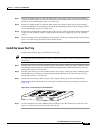
Install the Switch in the Rack
Even with the cards removed, the weight and bulk of the card cage mandates that three or more people
install it. Two installers can support and maneuver the Cisco MGX 8950 while a third secures it to
the
rack.
This section details the procedures necessary to install the Cisco MGX 8950 switch with a mechanical
lift in either a 19-inch or 23-inch rack.
• Install the Switch in a 19-Inch Rack, page 3-23
• Install the Switch in a 23-Inch Rack, page 3-24
Tip If the screw holes on the card cage are not aligned with the holes on the frame, place a flat-blade
screwdriver between the card cage and fan tray to raise the card cage. Then insert the screws and
tighten them. Then, remove the screwdriver from between the fan tray and card cage.
Warning
Never attempt to lift the chassis with the handles on the power supplies, fan trays, or the switching
modules. These handles are not designed to support the weight of the chassis. Using them to lift or
support the chassis can result in severe damage to the equipment and serious bodily injury.
Warning
Two people are required to lift the chassis. Grasp the chassis underneath the lower edge and lift with
both hands. To prevent injury, keep your back straight and lift with your legs, not your back. To prevent
damage to the chassis and components, never attempt to lift the chassis with the handles on the
power supplies or on the interface modules. These handles were not designed to support the weight
of the chassis.
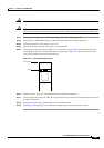
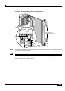
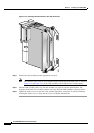
Install the Switch in a 19-Inch Rack
Complete the following steps to install the Cisco MGX 8950 switch in a 19-inch rack:
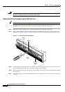
Step 1 Attach one mid-mounting bracket to each side of the Cisco MGX 8950 switch before installing the unit
in a rack.
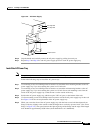
Step 2 Have two people position the switch to the desired position in the rack or if spacers are used, slide the
switch across the spacers and position it in the rack.
Note Maintain a gap of ~.060 inches (1/16 inch) between units. A spacer may be used.
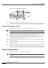
Step 3 Use the 10-32 truss head screws to secure the switch to the mid-mounting rails.