


3-18
Cisco MGX 8950 Hardware Installation Guide
Release 3, Part Number 78-14147-02 Rev. A0, November 2002
Chapter 3 Installing a Cisco MGX 8950
Installation Procedures
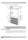
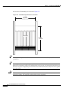
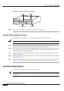
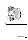
Figure 3-9 AC Power Supply Tray—Front View
Step 6 Repeat Step 1 through Step 5 to install a second AC power supply tray.
Install the AC Power Supplies in the Trays
Complete the following steps to re-install the power supplies that you have removed:
Caution Do not use a power screwdriver on captive screws.
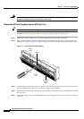
Step 1 Slide each AC power supply into the AC power supply tray. You will encounter a slight resistance as you
slide the AC power supply; apply even pressure to ensure full connector mating.
Step 2 Secure each AC power supply to the tray by tightening the captive screw at the front bottom of each AC
power supply, as shown in
Figure 3-8. For slots without a power supply, the hinged door on the tray
should already have a removable blank panel.
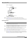
Step 3 Rotate the hinged door and tighten the captive retainer screw in the center of the hinged door using a
flat-blade screwdriver.
Step 4 Replace the air intake grille by putting the lower hooks over the hinged panel and then rotating the grille
until it snaps in place.
Step 5 Repeat Step 1 through Step 4 to reinstall the AC power supplies in a second AC power supply tray. Refer
to Table 1-13 to verify that you have the correct number of power supplies needed for your system.
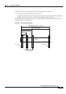
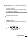
Install the Air Intake Plenum
Complete the following steps to install the air intake plenum:
Tip If a component requires more than two screws to install it in the rack or cabinet, install the two bottom
screws first.
17672
1200W
D
C
A
C
1200W
D
C
A
C
1200W
D
C
A
C
1200W
D
C
A
C
Air intake grille Front flange
Blank panel
Release