


C-9
Cisco MGX 8950 Hardware Installation Guide
Release 3, Part Number 78-14147-02 Rev. A0, November 2002
Appendix C Earthing and Bonding Recommendations
Bonding and Grounding the Cisco MGX 8950
in ITU-T recommendation K.27, the isolated and non-isolated ground systems can form a mixed
grounding system. The potential between any points in the ground system—whether or not the ground
system is mixed—must not exceed 2% of the referenced voltage (2% of 48 volts is 960 millivolts).
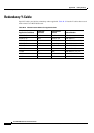
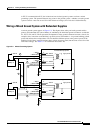
Wiring a Mixed Ground System with Redundant Supplies
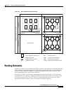
A mixed ground system appears in Figure C-2. This figure shows safety and earth grounds and the
primary and redundant DC sources Battery A and Battery B. Individual ground conductors are labeled
Z1, Z2, Z3, Z4, and Z5. The Z represents the impedance of the ground conductor between a chassis, for
example, and a connection to the building’s ground system. The numbers 1–4 represent building ground
points and indicate that an impedance can exist between different points in the ground system of the
building. Each of these symbols indicate that a voltage drop may result (but must not exceed 2% of the
referenced voltage). See
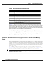
Table C-1 for a definition of each Z1–Z5.
Figure C-2 Mixed Grounding System
Battery A
Nonisolated equipment
– 48V-A
T
– 48V-A
– 48V-A
logic power
+–
– 48V-B
1
1
B
2
B
T
T
Safety ground
Safety ground
Safety ground
– 48V-A RTN
– 48V-A
– 48V-A RTN
– 48V-B
– 48V-B RTN
– 48V-B
– 48V-B RTN
Safety ground
Battery B
– 48V-B
+–
Isolated equipment
– 48V-A logic power
– 48V-B
2
4
T
Z1
Z1
Z1
Z1
Z2
Z2
Z2
Z2
Z3
3
Z4
Z5
28311