


1-5
Cisco MGX 8950 Hardware Installation Guide
Release 3, Part Number 78-14147-02 Rev. A0, November 2002
Chapter 1 Product Overview
Module Configurations
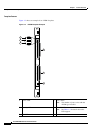
1+1 Card and APS Line Redundancy—Intercard
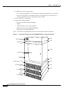
Maximum fault tolerance is achieved when both card and APS line redundancy are used. This
configuration protects the front cards, back cards, and lines independently. In this configuration, two
card sets (front and back cards) are installed in adjacent slots in the front and back of the switch: one is
configured as primary and the second is configured as secondary. For each connection on the primary
card set, a corresponding connection must be made on the secondary (redundant) card set.
A failure on the active front card causes a switchover to the standby front card. The standby front card
becomes active and continues to support calls over the line that was active at the time of failure. The
active line can be either the working or the protection line. A front card failure or switchover does not
trigger a change in the active APS line.
If the working line is active and fails, or if the back card to which the working line is connected fails,
communications traffic is rerouted through the protection line and the back card to which it is connected.
Correspondingly, if the protection line is active and fails, or if the back card to which the protection line
is connected fails, communications traffic is rerouted through the active line and the back card to which
it is connected. Software configuration options can enable or disable an APS reversion, in which an
automatic switchback occurs when the working line recovers from its previous failure.
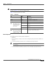
Consider the following requirements when planning a 1+1 card and APS line redundancy configuration:
• The primary and secondary front cards must be placed in adjacent slots, and the card sets must be
identical. You cannot pair nonmatching card sets.
• The primary and secondary back cards must be present in an APS connector, which is installed in
the rear of the switch.
• The primary and secondary cards can be configured the same so that switchover occurs faster
because the standby card does not have to download the configuration from the active card.
• The switches at both ends of the APS lines must be configured for APS, and the role of each line
(working or protection) must be the same at both ends of the line.
• The working line must be configured on the active back card.
• The protection line can be identified on the standby back card. Using a different back card provides
greater fault tolerance.
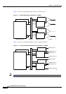
1:1 APS Line Redundancy—Intracard
1:1 APS line redundancy enables a standalone front card to use redundant lines, both of which are
connected to the same back card. Intracard APS provides line redundancy at the expense of port density.
For example, configuring APS line redundancy for the upper bay behind an AXSM-4-622 card would
reduce the port count from 2 to 1.
In this configuration, the working and protection lines connect to the same back card. The working line
is the primary communication line, and the protection line takes over if the working line fails. If the
protection line is active and fails, and if the working line has recovered from a previous failure, the
working line takes over.
Consider the following requirements when planning a 1:1 APS line redundancy configuration:
• The working line and the protection line must connect to adjacent ports on the same back card.
• The working line must be assigned to an odd-numbered port and the protection line must be assigned
to an even-numbered port. For example, the working line could be on port 1 and the protection line
on port 2.