


Tables
16
Cisco MGX 8950 Hardware Installation Guide
Release 3, Part Number 78-14147-02 Rev. A0, November 2002
Table 3-1 Installation Checklist—Cisco MGX 8950 System 3-2
Table 3-2 AC Power Cable Connections 3-36
Table 3-3 Interconnect Power Connections for DC 3-40
Table 3-4 Terminal Settings 3-45
Table A-1 Cisco MGX 8950 System Specifications A-1
Table A-2 AXSM Physical Specifications A-2
Table A-3 PXM45 Specifications A-3
Table A-4 RPM-PR Physical Specifications A-4
Table A-5 RPM-XF Specifications A-5
Table B-1 Trunk Cables B-1
Table B-2 T3 Connector Pin Assignments B-1
Table B-3 E3 Trunk Cables B-2
Table B-4 E3 Connector Pin Assignments B-2
Table B-5 DC Power Wiring B-2
Table B-6 AC Power Cables B-3
Table B-7 Maintenance and Control Port Cabling B-3
Table B-8 Maintenance and Control Port Pin Assignments B-4
Table B-9 External Clock Cabling B-4
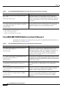
Table B-10 RJ48 BITS Clock Connector Pin Outs B-5
Table B-11 External Alarm Cabling B-5
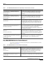
Table B-12 Network Alarm Pin Assignments B-5
Table B-13 PXM-UI-S3 Pin Assignment on the Alarm Connector B-6
Table B-14 Standard Cables Available from Cisco B-7
Table B-15 Y-Cable Product Names for Applicable Cards B-8
Table C-1 Ground Point Descriptions for Mixed Grounding C-10
Table C-2 Wire Gauge for Current Loads over Copper Wire Lengths C-11
Table C-3 Resistance for Each Gauge of Copper Wire C-11