


3-49
Cisco MGX 8950 Hardware Installation Guide
Release 3, Part Number 78-14147-02 Rev. A0, November 2002
Chapter 3 Installing a Cisco MGX 8950
Installation Procedures
Connect DC Power to the Switch
Complete the following steps to connect DC power to the switch:
Note Connect the Cisco MGX 8950 switch only to a –48 VDC source that complies with the Safety Extra Low
Voltage (SELV) requirements in IEC 60950/EN 60950.
If you are installing redundant DC PEMs, you can connect to the same power source if you do not require
the additional fault tolerance offered when using separate power sources.
Step 1 Verify that the power source to the switch is turned off and that the circuit breaker on the DC PEM is off.
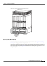
Step 2 Use a Phillips-head screwdriver to remove the two screws that hold the plastic cover over the terminal
block on the DC PEM (see
Figure 3-32 for location).
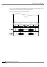
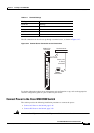
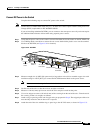
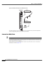
Figure 3-32 DC-PEM
Step 3 Measure enough wire (6 AWG [10 square mm] or larger three-wire solid or stranded copper wire with
insulation rating for 140°F [60°C]) to connect the DC PEM terminal block to the power source.
Note Cisco recommends using the Panduit LC AS6-10-L.
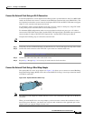
Step 4 Cut the ends of the wire so that the ends are straight, not slanted.
Step 5 Measure 1/4 inch (6 mm) up from one end of the wire and place a mark at that point.
Step 6 Use a wire stripper to remove 1/4 inch (6 mm) of the covering from the end of the wire. Trim the end of
the covering so that it is straight, not slanted.
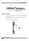
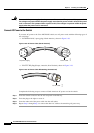
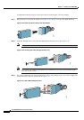
Step 7 Attach a ring or space lug on the end of copper wire you prepared in Step 6. The stripped part of the wire
must be fully inserted so that no bare wire is exposed.
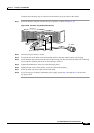
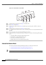
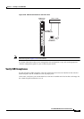
Step 8 Attach the end of the wire with the ring or space lug to the 48 VDC return, as shown in Figure 3-33.
DC
J2 output
connector
-48V DC
-48V DC 50A
-48V
RTN
J2
J1
-48V DC 50A
-48V
RTN
43978
Circuit breaker
J1 output
connector
DC OK
LED
Plastic
cover
Terminal
block 2
Terminal
block 1