


3-11
Cisco MGX 8950 Hardware Installation Guide
Release 3, Part Number 78-14147-02 Rev. A0, November 2002
Chapter 3 Installing a Cisco MGX 8950
Installation Procedures
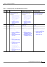
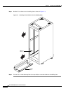
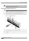
Step 3 Place another external, toothed star washer or lock washer onto the studs.
Step 4 Use a wrench to tighten a nut onto the threaded studs.
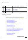
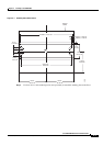
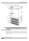
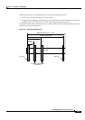
Measure Rack Space
Before you install the Cisco MGX 8950 switch and its related components, calculate the total rack space
required to install your system. See
Table 2-2 on page 2-13 for the Cisco MGX 8950 dimensions and
rack units (RUs) required.
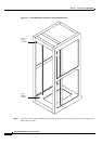
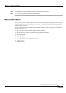
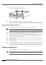
System components must be installed in the rack in the following sequence, beginning at the bottom of
the rack (see
Figure 3-4):
1. AC power supply tray with power supply modules (optional)
2. Second AC power supply tray with power supply modules (optional)
3. Air intake plenum
4. Lower fan tray
5. Cisco MGX 8950 switch (with optional door)
6. Upper fan tray
7. Exhaust plenum