


3-40
Cisco MGX 8950 Hardware Installation Guide
Release 3, Part Number 78-14147-02 Rev. A0, November 2002
Chapter 3 Installing a Cisco MGX 8950
Installation Procedures
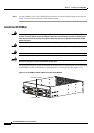
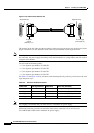
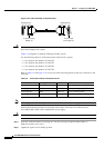
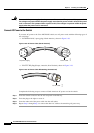
Figure 3-22 Cable Assembly for System Power
Caution The connectors on the DC cables are keyed to ensure proper cabling to the DC PEM. Improper cabling
may cause damage to the system.
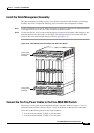
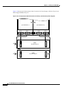
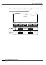
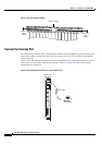
Figure 3-23 diagrams in detail the cabling for the DC system.
Use the following cables to install interconnect cables for DC systems:
• Cisco Systems part number 72-2424-XX
• Cisco Systems part number 72-2425-XX
• Cisco Systems part number 72-2426-XX
• Cisco Systems part number 72-2427-XX
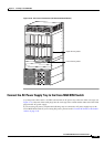
Refer to Table 3-3 and Figure 3-23 to assist you with connecting the DC power tray connectors to the
card cage:
Note Cisco highly recommends that you install and use a redundant DC power supply.
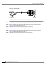
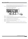
Perform the following procedure to install the interconnect connections for an DC-Powered
Cisco
MGX 8950 switch with a redundant DC power supply:
Caution Do NOT use power tools for this procedure.
Step 1 Insert the connector labeled “Card Cage A1” into the card cage receptacle labeled “PSA 1.”
Push the connector in to seat it.
Step 2 Tighten the captive screws firmly by hand.
Card Cage A1
PS Tray 1
J1
47224
To power supply
(PEM1 J1)
To card cage
(card cage A1)
Alignment keyAlignment key
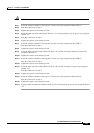
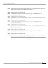
Ta b l e 3-3 Interconnect Power Connections for DC
Cable Label Card Cage Connection Cable Label PEM Connection
Card Cage A1 PSA 1 PEM 1 J1 J1 on primary (bottom) PEM
Card Cage B1 PSB 1 PEM 2 J1 J1 on secondary (top) PEM
Card Cage B2 PSB 2 PEM 2 J2 J2 on secondary PEM
Card Cage A2 PSA 2 PEM 1 J2 J2 on primary PEM