


4-5
Cisco MGX 8950 Hardware Installation Guide
Release 3, Part Number 78-14147-02 Rev. A0, November 2002
Chapter 4 Maintaining the Cisco MGX 8950 Switch
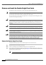
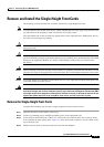
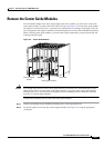
Remove and Install the Double-Height Front Cards
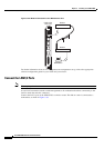
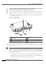
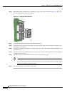
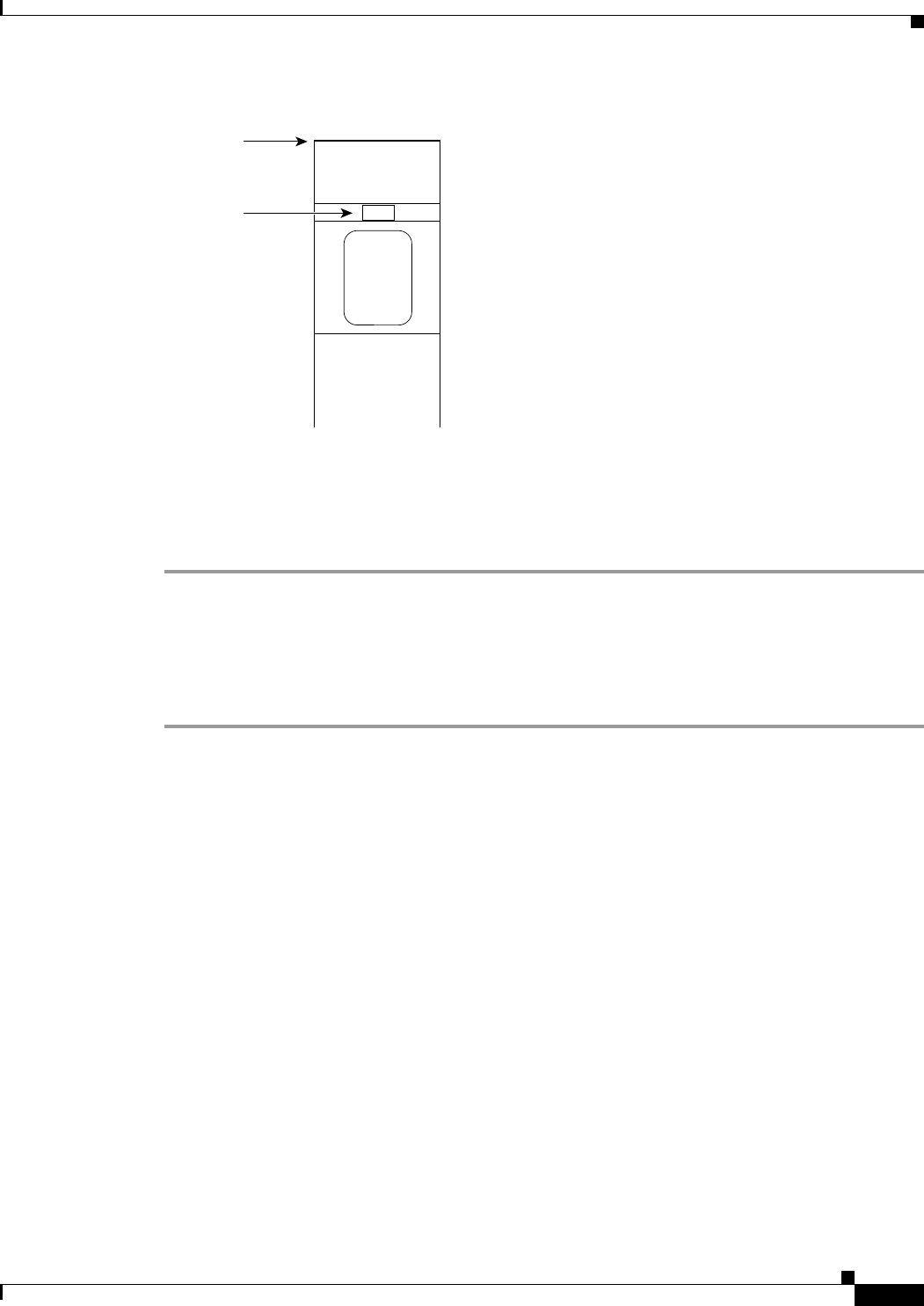
Figure 4-3 Extractor Lever
Step 4 Pull the extractor levers to disconnect the front card from the midplane.
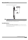
Step 5 Gently pull the front card out of the card cage. Keep the front card level and make sure that it does not
hit the one beneath it.
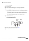
Step 6 Either replace the front card that you remove or insert a blank faceplate in the empty slot.
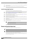
Install the Double-Height Front Cards
Complete the following steps to install double-height front cards in the chassis:
Step 1 Connect a grounding strap to the ESD grounding jack or to the equipment rack.
Step 2 See the “Card Installation Guidelines” section on page 2-9 to verify that there are no bent pins, bent
dividers, or damaged connectors on the front cards.
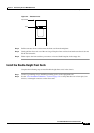
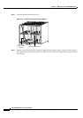
Top of card
Slot
H8293