


3-19
Cisco MGX 8950 Hardware Installation Guide
Release 3, Part Number 78-14147-02 Rev. A0, November 2002
Chapter 3 Installing a Cisco MGX 8950
Installation Procedures
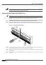
Step 1 Place the air intake plenum on a flat and stable surface (for example, a table top) and use mounting
screws and a Phillips-head screwdriver to attach the front-mounting brackets to the sides of the air intake
plenum if you are installing the system in a 23-inch rack.
Step 2 Place the air intake plenum on a flat and stable surface (for example, a table top) and use mounting
screws and a Phillips-head screwdriver to attach the mid-mounting brackets to the air intake plenum if
you are installing the system in a 19-inch rack.
Step 3 Position the air intake plenum, which occupies 3 RUs of space, either at the bottom of the configuration
or rack (for a DC-powered system) or directly above the AC power supply tray (for an AC-powered
system).
Step 4 Use four mounting screws and a Phillips-head screwdriver to bolt the air intake plenum in the rack. See
Figure 3-4 for the correct placement of the air intake plenum.
Install the Lower Fan Tray
Complete the following steps to install the lower fan tray:
Tip If a component requires more than two screws to install it in the rack or cabinet, install the two bottom
screws first.
Step 1 Place the lower fan tray on a flat and stable surface (for example, a table top) and use mounting screws
and a Phillips-head screwdriver to attach the front-mounting brackets to the lower fan tray if you are
installing the system in a 23-inch rack.
Step 2 Place the lower fan tray on a flat and stable surface (for example, a table top) and use mounting screws
and a Phillips-head screwdriver to attach the mid-mounting brackets to the lower fan tray if you are
installing the system in a 19-inch rack.
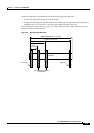
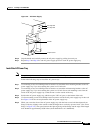
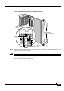
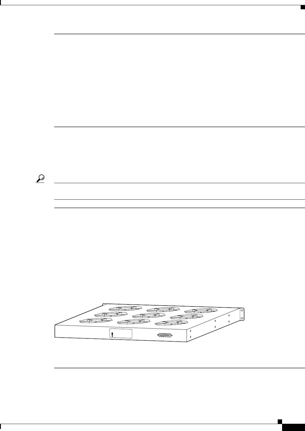
Step 3 Position the lower fan tray, which occupies 1 RU of space, directly above the air intake plenum.
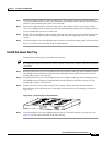
Ensure that the air flow direction arrow on the back of the lower fan tray is pointing up, as shown in
Figure 3-10.
Figure 3-10 Lower Fan Tray Air Flow Direction
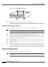
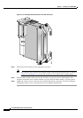
Step 4 Use four mounting screws and a Phillips-head screwdriver to bolt the lower fan tray in the rack. See
Figure 3-4 for the correct placement of the lower fan tray.
66951
UP
AIR FLOW
DIRECTION