


3-28
Cisco MGX 8950 Hardware Installation Guide
Release 3, Part Number 78-14147-02 Rev. A0, November 2002
Chapter 3 Installing a Cisco MGX 8950
Installation Procedures
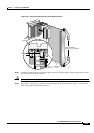
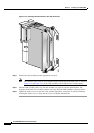
Step 6 Once the back card is installed in the switch, apply even pressure to the top and bottom of the faceplate
to fully seat the back card.
Step 7 Use the flat-head or Phillips tip of the 3-in-1 tool to tighten the two captive screws on the back
card
faceplate.
Note Tighten the top and bottom captive screws in increments to prevent misalignment of the card.
Do not overtighten the screws, but tighten the screws to secure the card.
Step 8 Repeat Step 2 through Step 7 for each back card that you are reinstalling in the switch.
Step 9 Install blank faceplates over any empty slots.
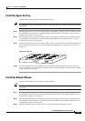
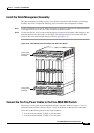
Reinstall the Front Cards
Note All cards must be fully seated in the switch. When installing the front card, apply even pressure to the
top and bottom of the faceplate to make sure that the card is fully seated.
The card should slide in and out with only slight friction on the adjacent board’s EMI gaskets. Do not
force the card. Investigate any binding.
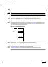
Single-height front cards have an extractor lever at the top of the faceplate to secure them into the card
cage. Double-height front cards have an extractor lever at both the top and the bottom of the faceplate.
Caution If the AXSM-1-2488 or AXSM-1-2488/B front cards are installed with incorrect back cards, you may
damage the cards.
Caution To prevent damage to components on the bottom side of a card, support the faceplate and keep the card
level while sliding it into the switch.
Warning
Blank faceplates and cover panels serve three important functions: they prevent exposure to
hazardous voltages and currents inside the chassis; they contain electromagnetic interference (EMI)
that might disrupt other equipment; and they direct the flow of cooling air through the chassis. Do not
operate the system unless all cards, faceplates, front covers, and rear covers are in place.
Complete the following steps to reinstall a front card into the Cisco MGX 8950 switch:
Step 1 Refer to the notes you made when you recorded the location of each card to ensure that the cards are
installed in the correct slots. For slot assignments for your system, refer to the
“Cisco MGX 8950 Switch
Compartment” section on page 1-3.
Step 2 See the “Card Installation Guidelines” section on page 2-9 to verify that there are no bent pins, bent
dividers, or damaged connectors on the back cards.
Step 3 Verify that the extractor lever(s) are in the unlatched position.