


3-52
Cisco MGX 8950 Hardware Installation Guide
Release 3, Part Number 78-14147-02 Rev. A0, November 2002
Chapter 3 Installing a Cisco MGX 8950
Installation Procedures
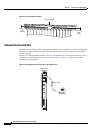
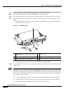
Complete the following steps to connect the external clock using the wire-wrap adapter:
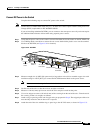
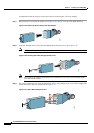
Step 1 Remove the pin cover from the adapter (see Figure 3-35). The pin cover provides ESD shielding.
Figure 3-35 Removing the Pin Cover from the Adapter
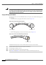
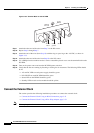
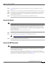
Step 2 Insert the shielded clock source cable through the hole of the pin cover. See Figure 3-36.
Note A shielded clock source cable must be used to ensure EMI containment.
Figure 3-36 Inserting the Cable through the Pin Cover
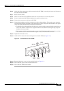
Note The length of the exposed (unshielded) wires should be 2 to 4 inches. The maximum length
must not exceed 4 inches.
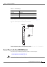
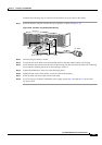
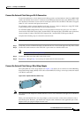
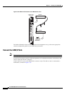
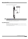
Step 3 Use a wire-wrapping tool to wrap the shield drain wire to the ground pin (pin 3 or 6) of the adapter. The
shield drain wire is the bare wire shown in
Figure 3-37.
Figure 3-37 Wires Wire-Wrapped to Pins
52803
5
6
7
8
52805
1
2
3
4
5
6
7
8
53281
1
2
3
4