


1-15
Cisco MGX 8950 Hardware Installation Guide
Release 3, Part Number 78-14147-02 Rev. A0, November 2002
Chapter 1 Product Overview
System Hardware Components
Faceplate Features
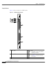
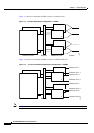
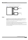
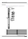
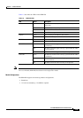
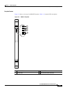
Figure 1-6 shows a close-up of a PXM45/B faceplate. Table 1-7 contains LED descriptions.
Figure 1-6 PXM45/B Faceplate
1 Controller port LED 7 History LED
2 Critical alarm LED 8 Ethernet LED
3 Major alarm LED 9 Alarm cut off button
4 Minor alarm LED 10 History button
5 Power supply LEDs (DC-A and DC-B) 11 System status LED
6 Alarm cut off LED
84491
CNTLR Port
CR
MJ
MN
DC-A
DC-B
ACO
HIST
ENET
ACO
HIST
SYSTEM
STATUS
PXM45/B
CNTLR Port
CR
MJ
MN
DC-A
DC-B
ACO
HIST
ENET
ACO
HIST
1
2
3
4
5
5
6
7
8
9
10
11