


3-14
Cisco MGX 8950 Hardware Installation Guide
Release 3, Part Number 78-14147-02 Rev. A0, November 2002
Chapter 3 Installing a Cisco MGX 8950
Installation Procedures
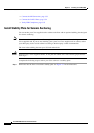
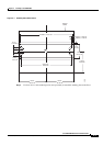
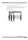
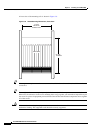
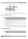
A front view of the mounting rails is shown in Figure 3-6.
Figure 3-6 Rack Mounting Dimensions, Front View
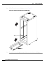
Tip If a component requires more than two screws to install it in the rack or cabinet, install the two bottom
screws first.
Tip Do not tighten the screws completely (maybe half of a turn) until all components are mounted to the rack.
Otherwise, the tolerances in the screw mounting holes can go against you and make it impossible to put
the screws in a piece of equipment you install later. Once all the rack mounted components are in, tighten
all of the screws.
Caution Make sure that mounting the equipment does not create a hazardous condition due to uneven
mechanical loading. The equipment rack should be securely supported.
17.750"
Minimum
between rails
22.750"
13 RMUs
MGX 8950
1 2 3 4 5 6 7 8 9 10 11 12 13 14 15 16
44140