


1-13
Cisco MGX 8950 Hardware Installation Guide
Release 3, Part Number 78-14147-02 Rev. A0, November 2002
Chapter 1 Product Overview
System Hardware Components
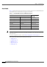
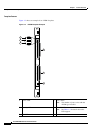
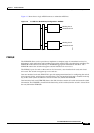
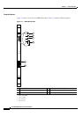
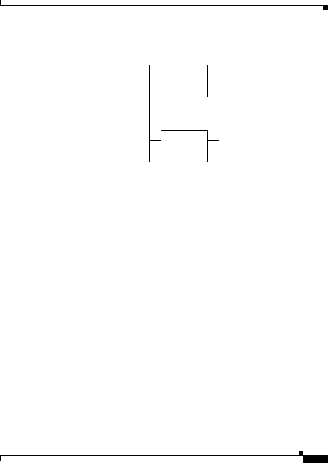
Figure 1-5 shows how a single AXSM connects to redundant APS lines.
Figure 1-5 1:1 APS Line Redundancy Configuration—AXSMs
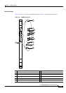
PXM45/B
The PXM45/B allows service providers to implement a complete range of narrowband services for
high-density edge applications and broadband aggregation with 45 Gbps of nonblocking switching. The
PXM45/B can also be used exclusively for broadband aggregation and backbone functions. The
PXM45/B controls the switch and supports external interfaces for user access.
The PXM45 is part of a card set that consists of a front card, a user interface back card, and a hard
drive
card. The switch can support up to two card sets.
One user interface back card (PXM-UI-S3) provides management interfaces for configuring the switch,
using external clocks, and triggering external alarms. The user interface back card is installed in the top
bay of the switch (when the switch is viewed from the rear) behind the PXM45/B.
One hard drive back card (PXM-HD) houses the disk drive that contains all switch and network-related
information. The PXM-HD is installed in the bottom bay of the
switch (when the switch is viewed from
the rear) behind the PXM45/B.
AXSM front card AXSM back cards
Working line B
45055
Midplane
Protection line B
Working line A
Protection line A