


4-10
Cisco MGX 8950 Hardware Installation Guide
Release 3, Part Number 78-14147-02 Rev. A0, November 2002
Chapter 4 Maintaining the Cisco MGX 8950 Switch
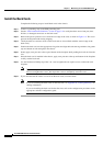
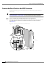
Remove and Install the Back Cards
Install the Back Cards
Complete the following steps to install back cards in the chassis:
Step 1 Connect a grounding strap to the ESD grounding jack.
Step 2 See the “Card Installation Guidelines” section on page 2-9 to verify that there are no bent pins, bent
dividers, or damaged connectors on the back cards.
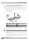
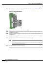
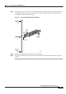
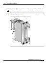
Step 3 Remove the plastic protective cover from the rear edge of the card, as shown in Figure 4-4. This cover
protects the alignment tabs during shipping.
Step 4 7Verify that the two extractor levers on the back card are closed (flush with the vertical edge of the
back cards).
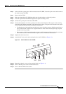
Step 5 Position the back card over the appropriate slot guides and align the back card edge with the slot guides
(top and bottom or left and right) in the chassis.
Step 6 Gently apply even pressure to the top and bottom of the faceplate while pushing the back card into the
slot.
Step 7 Once the back card is installed in the chassis, apply even pressure to the top and bottom of the faceplate
to fully seat the back card.
Step 8 Use the flat-head or Phillips tip of the 3-in-1 tool to tighten the two captive screws on the back card
faceplate.
Note Tighten the top and bottom captive screws in increments to prevent misalignment of the card.
Do not overtighten the screws, but torque the screws to adequately secure the card.
Step 9 If you disconnected the cables or wires from the back cards, reconnect them.
Note If you are installing the back cards for the first time, see Appendix B, “Cabling Summary” for
cabling information.
If you are installing the back card for the first time, refer to the configuration procedures in the
appropriate software configuration guide.