


3-50
Cisco MGX 8950 Hardware Installation Guide
Release 3, Part Number 78-14147-02 Rev. A0, November 2002
Chapter 3 Installing a Cisco MGX 8950
Installation Procedures
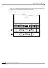
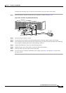
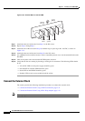
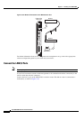
Figure 3-33 Terminal Block on the DC PEM
Step 9 Attach the other end of the wire from Step 7 to the DC source.
Step 10 Repeat Step 3 through Step 7.
Step 11 Attach the end of the wire (from Step 10) with the ring or space lug to the –48 VDC, as shown in
Figure 3-33.
Step 12 Attach the other end of the wire from Step 10 to the DC source
Step 13 Use a Phillips-head screwdriver and two screws to attach the plastic cover over the terminal block on the
DC PEM.
Step 14 Turn on the power source and turn the DC PEM power switch on
Step 15 Verify that the fans are running by listening or feeling for air movement. The following LEDs should
be
lit:
• AC and DC LEDs on each power supply should be green.
• DC OK LED on each DC PEM should be green.
• Status LED on the PXM45 should be green.
• Standby LED on each service module should be yellow.
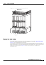
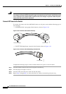
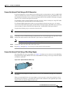
Connect the External Clock
The section provides the following installation procedures to connect the external clock:
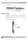
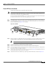
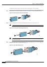
• Connect the External Clock Using an RJ-45 Connection, page 3-51
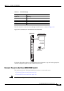
• Connect the External Clock Using a Wire-Wrap Adapter, page 3-51
Note This step is optional.
48 VDC
return
Safety
g
round
–48 VDC
38228
-48V
RTN