


3-26
Cisco MGX 8950 Hardware Installation Guide
Release 3, Part Number 78-14147-02 Rev. A0, November 2002
Chapter 3 Installing a Cisco MGX 8950
Installation Procedures
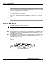
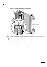
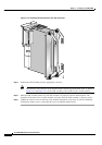
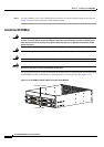
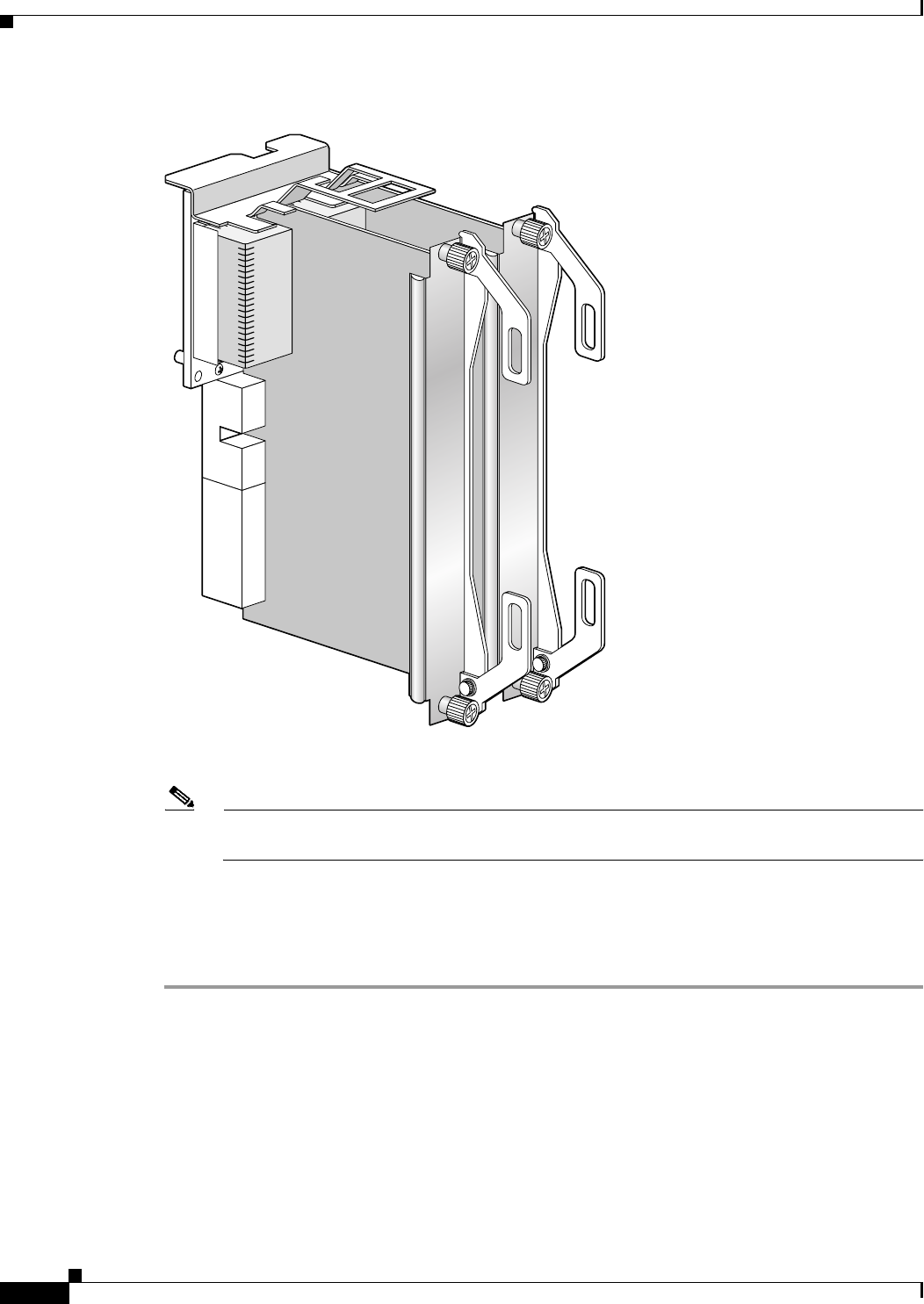
Figure 3-13 Installing Two Back Cards in the APS Connector
Step 4 Position the APS assembly into the appropriate card slots.
Note The extractor levers must be closed (flush with the vertical edge of the back cards, as shown in
Figure 3-12 and Figure 3-13) or the APS assembly will not slide into the switch properly.
Step 5 Slide the APS assembly all the way into the slot until it is properly seated in the backplane. The
faceplates of the back cards are flush with the card cage when the APS assembly is properly
seated.
Step 6 Tighten the captive screws on the back cards with the appropriate screwdriver. If you have difficulty
inserting the captive screws, verify that the screws are aligned with the holes.
4414444144