


1-10
Cisco MGX 8950 Hardware Installation Guide
Release 3, Part Number 78-14147-02 Rev. A0, November 2002
Chapter 1 Product Overview
System Hardware Components
Faceplate Features
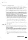
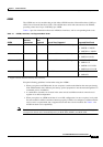
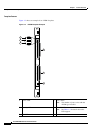
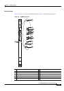
Figure 1-2 shows an example of an AXSM faceplate.
Figure 1-2 AXSM Faceplate Example
1 Active LED 4 Port x LEDs
Note The number of ports varies with the
AXSM type installed.
2 Standby LED 5 E3 or T3 LEDs
Note See Table 1-5 for details about the
LED support.
3 Fail LED
AXSM
32T1E1
ACT
STANDBY
FAI L
PORT1
PORT2
PORT3
PORT4
PORT5
PORT6
PORT7
PORT8
PORT9
PORT10
PORT11
PORT12
PORT13
PORT14
PORT15
PORT16
PORT18
PORT19
PORT17
PORT20
PORT21
PORT22
PORT23
PORT24
PORT25
PORT26
PORT27
PORT28
PORT29
PORT30
PORT31
PORT32
T1
E1
70885
5
4
4
ACT
STANDBY
FAIL
2
3
1