


B-3
Cisco MGX 8950 Hardware Installation Guide
Release 3, Part Number 78-14147-02 Rev. A0, November 2002
Appendix B Cabling Summary
AC Power Cabling
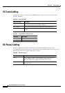
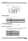
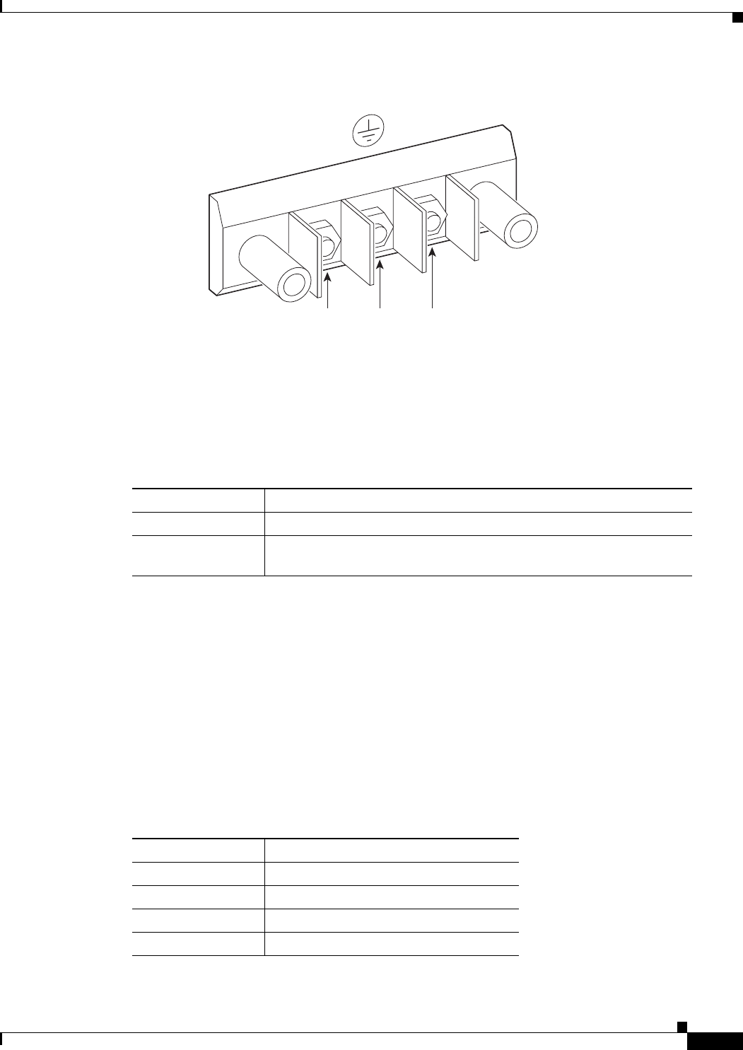
Figure B-1 DC Power Connections
AC Power Cabling
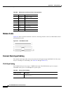
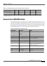
Table B-6 shows the power cords that Cisco can supply.
Control and Clock Cabling
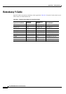
This section describes the cables that can connect to the PXM-UI-S3 card.
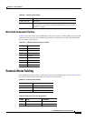
Maintenance and Control Ports
The maintenance (or modem) port and the control (or console) port connect a node to an ASCII terminal,
workstation, or modem for remote alarm reporting or system monitoring. See
Table B-7 for a description
of the cabling and Table B-8 for the pinout of the associated RJ48 connector.
48 VDC
return
Safety
g
round
–48 VDC
38228
-48V
RTN
Ta b l e B-6 AC Power Cables
Cable Parameter Description
Cable Provided with 10 feet (2.3 m) of 3-conductor wire with plug.
Customer End Plug 30A NEMA L620, 3-prong plug (United States)
For international use, the line cord is hard wired with an IEC309 plug.
Ta b l e B-7 Maintenance and Control Port Cabling
Cable Parameter Description
Interface EIA/TIA-232—both are DTE ports
Suggested Cable Uses only 8 conductor
Cable Connector RJ48, subminiature, male
Max. Cable Length 50 feet (15 m)