


3-12
Cisco MGX 8950 Hardware Installation Guide
Release 3, Part Number 78-14147-02 Rev. A0, November 2002
Chapter 3 Installing a Cisco MGX 8950
Installation Procedures
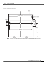
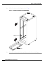
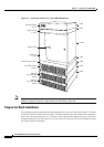
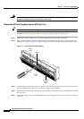
Figure 3-4 Component Locations in a Cisco MGX 8950 Switch
Note If you plan to expand your system to include more equipment in the future, allow space in the rack for
additions, keeping in mind the weight distribution and stability of the rack.
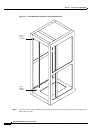
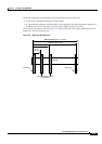
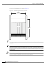
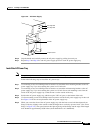
Prepare for Rack Installation
The minimum distance between left and right mounting rails (as you face the rack) must be 17.75 inches
or 45.08 cm. (Some 19-inch racks have only 17.50 inches between rails.) The width of the components,
such as the card cage and fan tray, is 17.72 inches. Each component has flanges that serve as the front
mounting brackets in a 19-inch rack. For a 23-inch rack, Cisco Systems offers special adapter brackets
that can be purchased separately.
43977
A
C
D
C
1200W
A
C
D
C
1200W
A
C
D
C
1200W
A
C
D
C
1200
W
A
C
D
C
1200W
A
C
D
C
1200W
A
C
D
C
1200W
A
C
D
C
1200W
Exhaust plenum
3.5 in.
2 RU
1 RU
10 RU
1 RU
3 RU
3 RU
3 RU
Upper fan tray
1.75 in.
Lower fan tray. 1.75 in.
Card cage
17.5 in.
Air intake plenum
5.25 in.
Optional
AC power tray
5.25 in
Optional
AC power tray
5.25 in
Status LEDs