


4-14
Cisco MGX 8950 Hardware Installation Guide
Release 3, Part Number 78-14147-02 Rev. A0, November 2002
Chapter 4 Maintaining the Cisco MGX 8950 Switch
Connect the Back Cards to the APS Connector
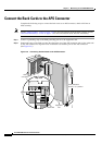
Connect the Back Cards to the APS Connector
Complete the following steps to connect the back cards to an APS connector, which will form an
APS
assembly:
Note See the “APS Assembly” section on page 1-48 for more information about the APS assembly and the
“APS Line Redundancy” section on page 1-4 for more information about APS line redundancy.
Step 1 Connect a grounding strap to the ESD grounding jack or to the equipment rack.
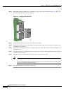
Step 2 Position the edge of the back card into the alignment slot of the APS connector and use the guide tabs
on the APS connector to align the holes on the back card with the pins on the APS connector.
(See
Figure 4-8.)
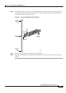
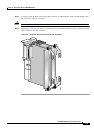
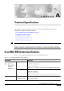
Figure 4-8 Connecting the Back Card to the APS Connector
Top view
APS
connector
Back card
Alignment
slot
Card extractors
shown in "in" position
44143
Guide tabsGuide tabs