


3-21
Cisco MGX 8950 Hardware Installation Guide
Release 3, Part Number 78-14147-02 Rev. A0, November 2002
Chapter 3 Installing a Cisco MGX 8950
Installation Procedures
Caution Do not use a power screwdriver on captive screws.
Caution When extracting a front card, keep the card level until it is completely extracted from the switch. Do not
allow the front cards to drop against the cards below them. This could damage components on the cards.
Step 1 Connect a grounding strap to the ESD grounding jack or to the equipment rack.
Step 2 Place the Cisco MGX 8950 switch on a flat and stable surface (for example, the floor).
Step 3 Open the front door on the switch, as necessary.
Step 4 Record the location of all the cards before you remove them.
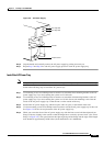
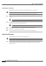
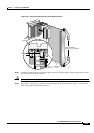
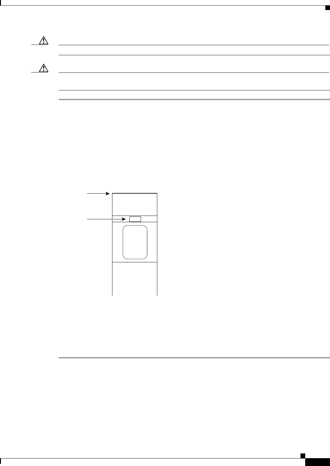
Step 5 Insert and press the flat-head tip of the 3-in-1 tool into the slot(s) of the extractor lever(s) at the top
(and bottom) of the front card until the latch(es) spring open.
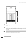
Figure 3-11 shows the location of the
lever slot in relation to the top of the front card.
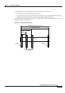
Figure 3-11 Front Card Extractor Lever
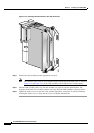
Step 6 Pull the extractor lever(s) to disconnect the front card from the midplane.
Step 7 Gently pull the front card out of the card cage. Keep the front card level and make sure that it does not
hit the one beneath it.
Step 8 Place the front card in an antistatic bag or on an antistatic bench.
Step 9 Repeat Step 5 through Step 8 for each front card that you are removing from the switch.
Top of card
Slot
H8293