


4-6
Cisco MGX 8950 Hardware Installation Guide
Release 3, Part Number 78-14147-02 Rev. A0, November 2002
Chapter 4 Maintaining the Cisco MGX 8950 Switch
Remove and Install the Double-Height Front Cards
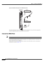
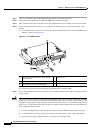
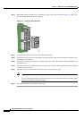
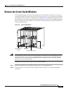
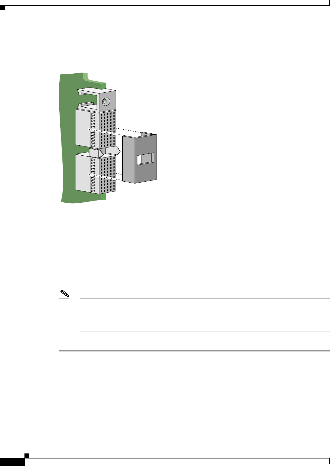
Step 3 Remove the plastic protective cover from the rear edge of the card, as shown in Figure 4-4. This cover
protects the alignment tabs during shipping.
Figure 4-4 Protective Cover Removal
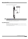
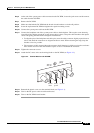
Step 4 Verify that the extractor levers are in the unlatched position.
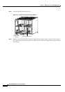
Step 5 Position the front card over the appropriate slot and align the front card edge with the slot guides (top
and bottom) in the chassis.
Step 6 Lift up and out on the extractor levers and gently apply pressure to the faceplate while pushing the front
card into the slot.
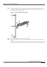
Step 7 Once the front card is installed in the chassis, apply even pressure to the top and bottom of the faceplate
to fully seat the front card.
Step 8 Press down on the extractor levers until they latch to secure the front card.
Note The double-height front cards have an extractor lever at the top and bottom of the front card.
If you are installing the front card for the first time, refer to the configuration procedures in the
appropriate software configuration guide.
Step 9 Close the front door on the switch, as necessary.
84165