


1-12
Cisco MGX 8950 Hardware Installation Guide
Release 3, Part Number 78-14147-02 Rev. A0, November 2002
Chapter 1 Product Overview
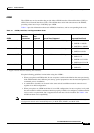
System Hardware Components
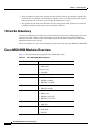
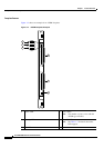
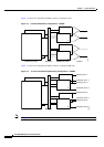
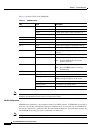
Figure 1-3 shows how redundant AXSMs connect to standalone lines.
Figure 1-3 Card Set Redundancy Configuration—AXSMs
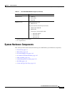
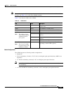
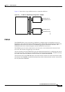
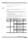
Figure 1-4 shows how redundant AXSMs connect to redundant APS lines.
Figure 1-4 1+1 Card and APS Line Redundancy Configuration—AXSMs
Note In Figure 1-4, the AXSM back card pairs are installed in an APS connector.
AXSM front cards AXSM back cards Y-cables
1
2
45056
Midplane
1
2
1
2
1
2
AXSM front cards AXSM back cards
1
2
45057
Midplane
1
2
1
2
1
2
Working line 1.1
Protection line 1.1
Protection line 1.2
Working line 1.2
Working line 2.1
Protection line 2.1
Protection line 2.2
Working line 2.2