


1-11
Cisco MGX 8950 Hardware Installation Guide
Release 3, Part Number 78-14147-02 Rev. A0, November 2002
Chapter 1 Product Overview
System Hardware Components
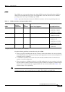
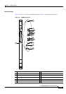
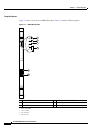
Note You can identify the AXSM by the product name, which is silk-screened on the front of the module
faceplate. See Table 1-4 for a list of the AXSMs available.
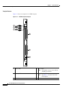
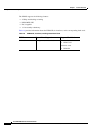
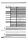
Table 1-5 describes the LEDs on the AXSMs.
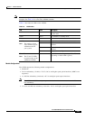
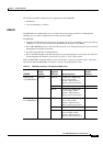
Module Configurations
The AXSM supports the following module configurations:
• Standalone
• Card set redundancy (Y-cable)—T3, E3, OC-3c and higher speed optical interfaces (MMF is not
supported)
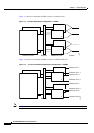
• 1:1 APS line redundancy (intracard)—OC-3c and higher speed optical interfaces
Note The AXSM-1-2488/B has only one port on the back card and cannot use intracard APS
line redundancy.
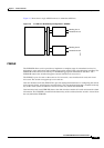
• 1+1 card and APS line redundancy (intercard)—OC-3c and higher speed optical interfaces
Ta b l e 1-5 AXSM LEDs
LED Status Description
ACT Green The AXSM card set (front card and back card) is
in active state.
STBY Yellow The AXSM is in standby mode.
FAIL Red A failure has been detected on the AXSM.
PORT x
Note The number of ports
varies with the type of
AXSM installed in
your system.
Green The port is active with no alarms detected.
Red The port is active and a local alarm has been
detected.
Yellow The port is active and a remote alarm has been
detected.
Off The port is not configured.
E3 or T3
Note The E3 and T3 LEDs
are present only on the
AXSM-16-T3E3/B.
Green The AXSM card set is operating in E3 or T3 mode
(depending on which LED is green).