


C-8
Cisco MGX 8950 Hardware Installation Guide
Release 3, Part Number 78-14147-02 Rev. A0, November 2002
Appendix C Earthing and Bonding Recommendations
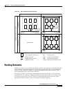
Bonding and Grounding the Cisco MGX 8950
7. In steel frame high-rise buildings, the shielding effects that the steel frame provides against
lightning strikes can help. For cables extending between floors, maximum shielding is obtained by
locating the cables near the center of the building. However, as stated above, cables enclosed in
metallic ducts may be located anywhere.
8. If the facility has over-voltage primary protection on telecommunication wires, it should have a low
impedance connection to the cable shield, if it exists, and to the surrounding CBN.
9. Over-voltage protectors are advisable at the AC power entrance facility if the telecommunication
building is located in an area where power lines are exposed to lightning. These protectors should
be bonded with low impedance to the CBN.
10. Mechanical connections in a protection path of the CBN whose electrical continuity may be
insufficient shall be bypassed by jumpers that are visible to inspectors. These jumpers shall comply
with IEC requirements for safety. However, for EMC applications, the jumpers should have low
impedance.
11. The CBN facilitates the bonding of cable shields or outer conductors of coaxial cables at both ends
by providing a low impedance path in parallel and in proximity to the cable shields and outer
conductors. Thus, most of the current driven by potential differences is carried by the highly
conductive members of the CBN. Disconnection of one cable shield for inspection should minimally
affect the current distribution in the CBN.
The main feature of a mesh-BN is the interconnection at many points of cabinets and racks of
telecommunications and other electrical equipment as well as multiple interconnections to the CBN.
Telecommunication techniques sometimes use circuits for signaling with earth return, for example, lines
with ground start, three wire inter-exchange connection. Equipment interconnected by these circuits
needs functional earthing. The signaling range is normally determined by the resistance of the current
path. Most of this resistance is contributed by the earth electrodes. The performance provided by the
earthing network via the main earthing terminal is generally sufficient for this signaling purpose.
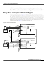
Bonding and Grounding the Cisco MGX 8950
To maintain the full EMI and EMC integrity of this equipment, the equipment must be bonded to an
integrated ground plane or a non-isolated ground plane network. The purpose is to mitigate the
damaging effects of electrostatic discharge or lightning. Refer to the latest edition of ITU-T
Recommendation K.27 or Bellcore GR-1089-CORE to ensure that the correct bonding and grounding
procedures are followed. As recommended in these documents, a frame bonding connection is provided
on the Cisco cabinet for rack-mounted systems. To see how to make a connection, see the
“Ground the
Frame Bonding Ground Connection for a Cisco-Supplied Rack” section on page 3-9.
Except for the AC power supply modules, every module in a rack-mount system uses the rack for
grounding. Therefore, the rack must connect to protective earth ground, and the equipment must be
secured to the rack so as to ensure good bonding.
A DC-powered node must have grounding conductors that connect at two separate locations:
• The grounding conductor provided with the supply source must connect to the correct terminal of
the Power Entry Module (PEM).
• A grounding conductor must connect to an appropriate terminal on a rack or the chassis of a node.
For DC-powered systems, Cisco has designed the Cisco MGX 8950 node and other WAN switches to
connect to a non-isolated ground system. In contrast, routers and other LAN equipment often use an
isolated grounding scheme. If properly wired together through an equalization connection as described