


3-30
Cisco MGX 8950 Hardware Installation Guide
Release 3, Part Number 78-14147-02 Rev. A0, November 2002
Chapter 3 Installing a Cisco MGX 8950
Installation Procedures
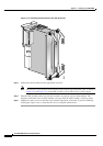
Warning
Never attempt to lift the chassis with the handles on the power supplies, fan trays, or the switching
modules. These handles are not designed to support the weight of the chassis. Using them to lift or
support the chassis can result in severe damage to the equipment and serious bodily injury.
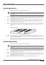
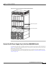
Install the Switch in a 19-Inch Rack
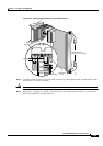
Complete the following steps to install the Cisco MGX 8950 in a 19-inch rack:
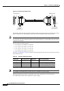
Step 1 Attach one mid-mounting bracket to each side of the Cisco MGX 8950 switch before installing the unit
in a rack.
Step 2 Use a lift to raise the switch to the desired position.
Step 3 Place two spacers (~.060 inches [1/16 inch] thick by ~2 inches by 30 inches fabricated from HDPE,
aluminium or cardboard), one on the left edge and one on the right edge, of the switch.
Step 4 Slide the switch across the spacers and position it in the rack.
Step 5 Use the 10-32 truss head screws to secure the switch to the mid-mounting rails.
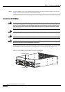
Install the Switch in a 23-Inch Rack
Complete the following steps to install the Cisco MGX 8950 in a 23-inch rack:
Note The components from a 23-inch mounting kit are used to install the switch in a 23-inch rack. For more
information about the mounting kits, see the “Rack-Mounting” section on page 2-20.
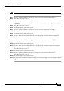
Step 1 Attach one front-mounting bracket to each side of the Cisco MGX 8950 switch before installing the unit
in a rack.
Note The rear mounting brackets cannot be installed before putting a unit in a 23-inch rack.
Step 2 Use a lift to raise the switch to the desired position.
Step 3 Place two spacers (~.060 inches [1/16 inch] thick by ~2 inches by 30 inches fabricated from HDPE,
aluminium or cardboard), one on the left edge and one on the right edge, of the switch.
Step 4 Slide the Cisco MGX 8950 across the spacers and position it in the rack.
Step 5 Use the 10-32 truss head screws to secure the switch to the front-mounting rails.
Step 6 Attach the rear mounting brackets to the rack.
Step 7 Use the 10-32 truss head screws to secure the switch to the rear mounting brackets.